|
|
|
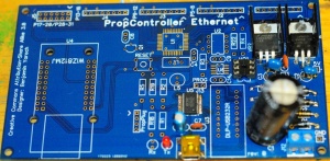
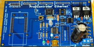
- Install four diodes (D1 - D4) P/N: 1N5817DICT-ND. The diodes have a strip (silver/grey) that must line up with the white silkscreen on the PCB.
|
|
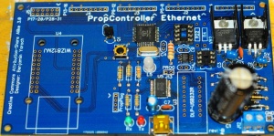
- Install the two 750 Ohm 1/4W resistors (R 6 - R 7) P/N: 750QBK-ND. The color bands are Violet, Green, Brown, Gold. The resistors have no polarity to worry about.
|
|
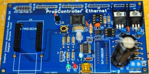
- Install the three 10k Ohm 1/4W resistors (R 4, R 8, R 22) P/N: 10KQBK-ND. The color bands are (Brown, Black, Orange, Gold). The resistors have no polarity to worry about.
|
|
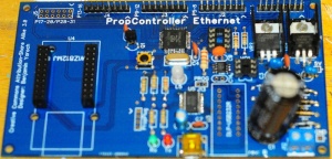
- Install the 0.1uF capacitor (C13) P/N: 445-2634-ND. This capacitor has no polarity to worry about.
|
|
- Install the two 47uF capacitors (C2 - C3) P/N: 445-2905-ND. These capacitors have no polarity to worry about.
|
|
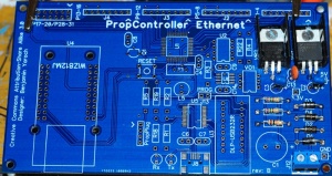
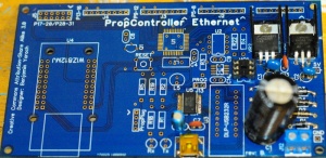
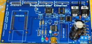
- Install the 5V Volt Regulator (VR1) P/N: 497-1404-5-ND. The regulator gets installed with the tab attached to the board with the heat-sink sandwiched in the middle. Bend the leads first with a pair of needle nose pliers, then attach the heat sink and voltage regulator to the board before soldering. The regulator should lie flat before being tightened down, otherwise the tab could come off.
- Install the 3.3 Volt Regulator (VR2) P/N: LM2937ET-3.3-ND. The regulator gets installed with the tab attached to the board with the heat-sink sandwiched in the middle. Bend the leads first with a pair of needle nose pliers, then attach the heat sink and voltage regulator to the board before soldering. The regulator should lie flat before being tightened down, otherwise the tab could come off.
|
|
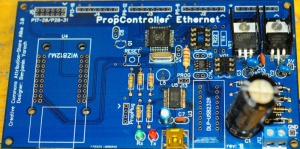
- Install the Terminal Block (J12) P/N: ED2600-ND. The terminal block gets installed with the holes facing outward.
|
|
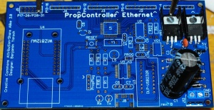
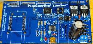
- Install the 2200uF capacitor (C1) P/N: P5143-ND. The capacitor _does_ have a polarity. The - - - stripe on the side of the capacitor goes into the Negative lead.
|
|
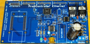
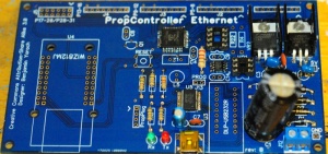
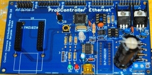
- Install the Zero Crossing chip (VO1) P/N: H11AA1M-ND. The chip gets installed with the indent matching the silkscreen and the dot denoting pin one matching the silkscreen. (Note: in the picture, you will see a socket, I prefer to put sockets on most of my chips, personal preference, not required).
|
|
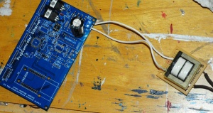
Test the Power
- Hook up a power source of 9-12V AC to the terminal block in the bottom right of the board.
|
|
- Measure the voltage at the 5V test point. It should be 5V give or take a few hundredths.
- Measure the voltage at the 3.3V test point. It should be 3.3V give or take a few hundredths.
USB Connection (SMT Option)
- Install the USB Mini Connector (J11) P/N: 732-2109-ND
|
|
- Install the FTDI 232 Chip (U5) P/N: 768-1007-1-ND. (Orientation Note)
|
|
- Install the 0.1uF capacitor (C7) P/N: 445-2634-ND. This capacitor has no polarity to worry about.
|

|
- Install the 4.7uF capacitor (C6) P/N: 445-2867-ND. This capacitor has no polarity to worry about.
|
|
- Install the 3mm Red LED (L1) P/N: 754-1243-ND (Orientation Note)
|
|
- Install the 3mm Green LED (L2) P/N: 754-1242-ND (Orientation Note)
|
|
USB Connection (Through Hole Option)
Main Board
- Install the Propeller IC (U1) P/N: P8X32A-Q44-ND. (Orientation Note)
|
|
- Install the 2K EEPROM Chip (U6) P/N: 24AA025E48-I/SN-ND (Orientation Note)
- Install the 512K EEPROM Chip (U2) P/N: 24LC512-I/P-ND (Orientation Note)
|
|
- Install the four 150 Ohm 1/4W resistors (R 1, R 5, R 18, R 19) P/N: 150QBK-ND . The color bands are Brown, Green, Brown, Gold. The resistors have no polarity to worry about.
- Install the 33k Ohm 1/4W resistor (R 2). P/N: 33KQBK-ND. The color bands are Orange, Orange, Orange, Gold. The resistors have no polarity to worry about.
|
|
- Install the 220 Ohm 1/4W resistor (R 3). P/N: 220QBK-ND. The color bands are Red, Red, Brown, Gold. The resistors have no polarity to worry about.
|
|
- Install the 5MHz Crystal (X1) P/N: XC1711-ND. There is no polarity or orientation to worry about.
|
|
- Install the 5mm Red/Green LED (L3) P/N: 754-1278-ND (Orientation Note)
- Install the Reset Switch (PB1) P/N: 450-1650-ND. (Orientation Note)
|
|
- Install the Transistor (Q1) P/N: P2N2222AGOS-ND. Make sure the body of the package lines up with the silkscreen on the PCB.
- Install the .01uF Capicator (C8) P/N: 399-4260-ND. This capacitor has no polarity to worry about.
|
|
- Install the Female Headers P/N: S7078-ND for the WizNet Module. They have no orientation, but make sure they sit flush with the PCB.
|
|
- Install the four 8-Position Male Headers (J1 - J4) P/N: WM4206-ND. Be sure they sit flush with the PCB. (It is helpful to tack 1 pin down and re-adjust if necessary)
|
|
- Install the 12-Position Male Header (J5) P/N: WM8124-ND. Be sure it sits flush with the PCB. (It is helpful to tack 1 pin down and re-adjust if necessary)
|
|
- Install the 2-Position Male Header (J13) P/N: WM8072-ND. Be sure that it sits flush with the PCB. (It is helpful to tack 1 pin down and re-adjust if necessary)
|


