Board Assembly
- Assembling the Ren-C should be fairly easy for most hobbyists.
- The following sequence of steps is by no means the only way to do this. It is simply a suggested order of events to achieve the desired goal.
|
|
|
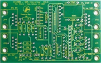
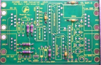
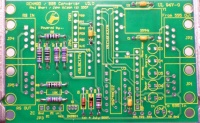
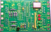
- Start by checking the PCB over for any production faults. Ensure that none of the tracks are shorted or open and that all holes are clear.
|
|
- Install two 22pF capacitors C1, C2 (PN# 581-SA102A220JAR). These capacitors have no polarity to worry about.
|
|
- Install two 0.1uF capacitors C3, C5 (PN# 581-SA105E104MAR). These capacitors have no polarity to worry about.
|
|
- Install three 27K ohm resistors R2, R6, R7 (PN# 271-27K-RC). Make sure that the resistors have a value of 27K ohm (red/violet/black/red/gold stripes). These resistors have no polarity to worry about.
|
|
- Install two 10K ohm resistors R8, R9 (PN# 271-10K-RC). Make sure that the resistors have a value of 10K ohm (brown/black/black/red/gold stripes). These resistors have no polarity to worry about.
|
|
- Install two 1K ohm resistors R4, R5 (PN# 271-1K-RC). Make sure that the resistors have a value of 1K ohm (brown/black/black/brown/gold stripes). These resistors have no polarity to worry about.
|
|
- Install 120 ohm resistor R3 (PN# 271-120-RC). Make sure that the resistor has a value of 120 ohm (brown/red/black/black/gold stripes). This resistor has no polarity to worry about.
|
|
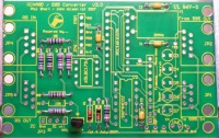
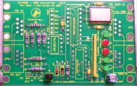
- Install zener diode D1 (PN# 78-1N5229B). The diode must go in correctly. The diode should have a black stripe on the orange/red body. Make sure that this stripe lines up with the stripe on the silk screen mask on the PCB.
|
|
- Install zener diode D2 (PN# 78-1N5239B). The diode must go in correctly. The diode should have a black stripe on the orange/red body. Make sure that this stripe lines up with the stripe on the silk screen mask on the PCB.
|
|
- Install transistor Q1 (PN# 512-2N3904TA). This device must also be correctly mounted. Make sure that the flat side of Q1 is aligned with the silk screen.
|
|
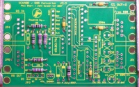
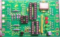
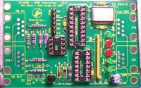
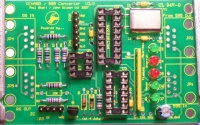
- Install five LEDs D3, D4, D5, D6, D7 (PN# 604-WP7104GT). The LEDs are polarized and must be mounted correctly. The short lead is the cathode and must be placed in the square solder pad. Another way to check is if your LED has a flat side to it then that side must be aligned with the silk screen.
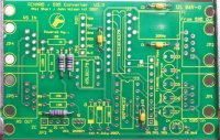
NOTE:
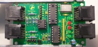
In the picture 2 red LEDs were substitued for the green ones called for in the BOM. This was done just as a personal preference.
|
|
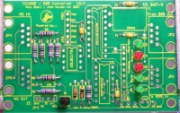
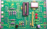
- Install resistor network RP (PN# 652-4610X-2LF-470). The resistor network should have a dot on it to indicate pin 1. Insert pin 1 of the resistor network into the square solder pad.
|
|
- Install crystal Y1 (PN# 815-AB-20-B2). The crystal has no polarity to worry about. It is helpful to carefully bend the leads for the desired component position prior to soldering them in-place.
|
|
- Install 10uF capacitor C4 (PN# 140-XRL10V10-RC). This capacitor is polarized and must be mounted correctly. The capacitor should have a black stripe on the body to indicate which lead is negative. The positive lead of the capacitor will be the longer lead. Make sure that the positive lead is placed in the square solder pad.
|
|
|
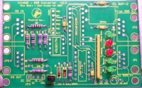
The next three items are optional but if you are going to use them then now would be a good time to install them.
INSTALLATION NOTE:
Pin 1 of the sockets must be aligned with the square solder pad. Another way to verify that you installed them correctly is to make sure that the notch on the socket is aligned with the notch on the PCB silk screen outline.
|
- Install the 18 pin IC socket (PN# 571-1-390261-5).
|
|
- Install the 14 pin IC socket (PN# 571-1-390261-3).
|
|
- Install the 8 pin IC socket (PN# 571-1-390261-2).
|
|
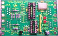
- Install 6-pin vertical header JP6 (PN# 571-1032396).
|
|
- Install 4-pin vertical header JP3 (PN# 571-1032394).
|
|
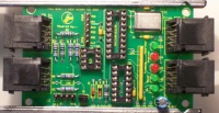
- Install four RJ45 jack sockets JP1, JP2, JP4, JP5 (PN# 571-5520251-4). Due to minor variations in manufacturing, some RJ45 sockets are a tighter fit than others. Care should be taken to ensure that the pins are aligned first before applying too much pressure to seat the locking lugs through the board.
|
|
|
INSTALLATION NOTE:
Ensure that pin 1 of the each IC is aligned with pin 1 of the respective socket. Can be verified by noting that the notch on the IC is aligned with the notch on the socket.
|
- Install IC U1 (PN# 595-SN65LBC179P) into the 8 pin IC socket.
- Install IC U2 (PN# 511-M74HC02) into the 14 pin IC socket.
- Install IC U3 (PN# 579-PIC16F627A-I/P) into the 18 pin IC socket.
|
|
CONGATULATIONS! You have just finished building your Ren-C board.
ZC and RENT requirements
When the REN64XB and RENC were first released, there was an extra board that was made available, the RENT. The function of the RENT was to provide power and a source of ZC to the controllers.
The RENC did not require separate power as it draws 5 V DC from the GRINCH board. What it does need is a source of ZC.
What is ZC? Zero Cross reference. When dimming, the RENC needs to know the start of the AC signal waveform, i.e. when it crosses over Zero V AC. A small sample of AC voltage is required to obtain the ZC.
There are a couple of options.
Option 1 - Use a small AC stepdown transformer (12.6V CT) and build a simple circuit to rectify the Low V AC to DC.
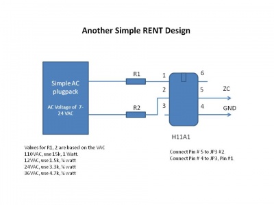
Option 2 - Use a small AC stepdown transformer (12.6V CT) and build a OPTOISOLATOR circuit to provide a source of ZC.
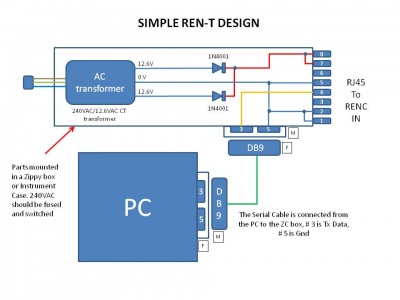
Option 3 - Use a centertap transformer with 2 diodes
http://doityourselfchristmas.com/forums/showpost.php?p=91084&postcount=23
Parts Listing (BOM)
|
|
|
|
|
PART NUMBER
(Mouser PN# unless noted) |
QTY |
REF |
NOMENCLATURE
|
| 815-AB-20-B2 |
1 |
Y1
|
20.000 MHz Crystal, HC49U case
|
| 581-SA102A220JAR |
2 |
C1,C2
|
22 pf, 200V NPO Axial Ceramic Capacitors
|
| 581-SA105E104MAR |
2 |
C3,C5
|
.1 uF, 50V, Z5U Axial Ceramic Capacitors
|
| 140-XRL10V10-RC |
1 |
C4
|
10 uF, 10V, Radial Aluminum Electrolytic Cap
|
| 604-WP7104GT |
5 |
D3-D7
|
Green Transparent LED, 3mm
|
| 604-WP7104IT |
. |
D3-D7
|
Red LED, 3mm (alternative to Green LED)
|
| 595-SN65LBC179P |
1 |
U1
|
RS485 Receiver/Transmitter (DIP8)
|
| 511-M74HC02 |
1 |
U2
|
Quad 2-Input NOR Gate (DIP14)
|
| 579-PIC16F627A-I/P |
1 |
U3
|
PICmicro - PIC16Fxxx Flash MCUs 1.75KB 224 RAM 16I/O
|
| 271-1K-RC |
2 |
R4,R5
|
Metal Film Resistor, 1K, 1/4W
|
| 271-10K-RC |
2 |
R8,R9
|
Metal Film Resistor, 10K, 1/4W
|
| 271-27K-RC |
3 |
R2,R6,R7
|
Metal Film Resistor, 27K, 1/4W
|
| 271-120-RC |
1 |
R3
|
Metal Film Resistor, 120, 1/4W
|
| 652-4610X-2LF-470 |
1 |
RP
|
Resistor Network, 470, 10-Pin SIP, Isolated Resistors
|
| 78-1N5229B |
1 |
D1
|
Diode, Zener, 4.3V, 0.5W
|
| 78-1N5239B |
1 |
D2
|
Diode, Zener, 9.1V, 0.5W
|
| 571-5520251-4 |
4 |
JP1,JP2,JP4,JP5
|
Modular Jack, Right-Angle, 8-8
|
| 571-1032394 |
1 |
JP3
|
Vertical Header, 4 Pin
|
| 571-1032396 |
1 |
JP6
|
Vertical Header, 6 Pin
|
| 571-41032390 |
. |
.
|
Vertical Header, 40 Pin (can be broken into smaller headers for above)
|
| 512-2N3904TA |
1 |
Q1
|
Transistor, NPN, small signal
|
| 571-1-390261-5 |
1 |
.
|
18 Pin DIP socket (optional)
|
| 571-1-390261-3 |
1 |
.
|
14 Pin DIP socket (optional)
|
| 571-1-390261-2 |
1 |
.
|
08 Pin DIP Socket (optional)
|
Below is the same parts list as above but it is formatted for direct importing into the Mouser BOM feature.
Just copy and paste the list as is. The last 3 parts listed correspond to the optional items listed above.
815-AB-20-B2	1
581-SA102A220JAR	2
581-SA105E104MAR	2
140-XRL10V10-RC	1
604-WP7104GT	5
595-SN65LBC179P	1
511-M74HC02	1
579-PIC16F627A-I/P	1
271-1K-RC	2
271-10K-RC	2
271-27K-RC	3
271-120-RC	1
652-4610X-2LF-470	1
78-1N5229B	1
78-1N5239B	1
571-5520251-4	4
512-2N3904TA	1
571-1032394	1
571-1032396	1
571-1-390261-5	1
571-1-390261-3	1
571-1-390261-2	1
Related Link
- Ren-C
- Renard Main Page
- Renard Firmware
- Part Substitutions
- VIXEN
- Glossary of DIYC Terms
- Electronic Symbols


.jpg)