Ren-W XBee Radio Configuration: Difference between revisions
Jump to navigation
Jump to search
Dirknerkle (talk | contribs) No edit summary |
Dirknerkle (talk | contribs) No edit summary |
||
| Line 28: | Line 28: | ||
*If you have two modules on each Ren-W board (a real luxury because of the added expense!), you can simply set the PANIDs of the two modules that will communicate with one another to the same PANID. See the "Point to Point" broadcasting example on the [[Ren-W Configuration Concepts]] page. | *If you have two modules on each Ren-W board (a real luxury because of the added expense!), you can simply set the PANIDs of the two modules that will communicate with one another to the same PANID. See the "Point to Point" broadcasting example on the [[Ren-W Configuration Concepts]] page. | ||
*However, in Alternate PTP mode with only ONE XBee module installed on a Ren-W board (XBee module in the TX position and jumper on JP5) XBee addressing is used instead. | *However, in Alternate PTP mode with only ONE XBee module installed on a Ren-W board (XBee module in the TX position and jumper on JP5) XBee addressing is used instead. With addressing, you have multiple options: | ||
:::::[[File:Xctu-3b.JPG |400px]] | :::::[[File:Xctu-3b.JPG |400px]] | ||
:::Notice the 16-bit source address option in the above window. You can insert a numerical address of your choosing here, such as 1001, 1002, 1003, etc. and leave the PANID the same for all modules. To create a daisy chain network, you would assign the "destination address high" of the first module to be the 16-bit address of the next module. You would continue this logic throughout your XBee network by assiging a specific 16-bit address to each module and then assigning the desired destination addresses. | :::Notice the 16-bit source address option in the above window. You can insert a numerical address of your choosing here, such as 1001, 1002, 1003, etc. and leave the PANID the same for all modules. To create a daisy chain network, you would assign the "destination address high" of the first module to be the 16-bit address of the next module. You would continue this logic throughout your XBee network by assiging a specific 16-bit address to each module and then assigning the desired destination addresses. | ||
Revision as of 04:08, 3 February 2010
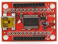
- You will need the free XCTU software from Digi International (www.digi.com) as well as an XBee programming board. An inexpensive programming board is available from SparkFun Electronics (www.sparkfun.com - XBee USB Explorer, SparkFun part # WRL-08687, about $25). Other programming boards are available and prices vary widely.
- 1. Verify that the programmer board is unplugged from the USB port, and plug the XBee module into the board.
- 2. Connect the programming board into the computer's USB port. Wait a few moments for the computer to recognize it.
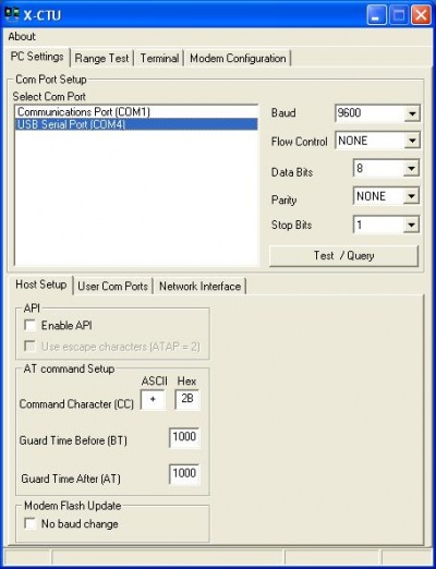
- 3. Start the XCTU software. Choose the proper communication port into which the programmer board is plugged.
- 4. Use the default communication parameters to begin (9600 baud, no flow control, 8 data bits, no parity, 1 stop bit). These are the default parameters for all XBee modules right out-of-the-box.
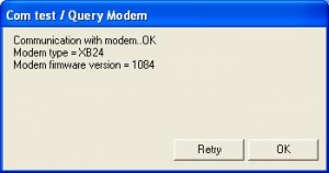
- 5. Connect to the XBee module by clicking the Test/Query button. After a few seconds, a confirmation box will appear that communication was successful. The box will also display the type and firmware version the XBee module is using. Close the test/query box to continue. Note: if a connection is not made, verify that the correct com port and baud rate was selected and try again. If still unsuccessful, retry using a different baud rate.
- 6. Select the Modem Configuration tab.
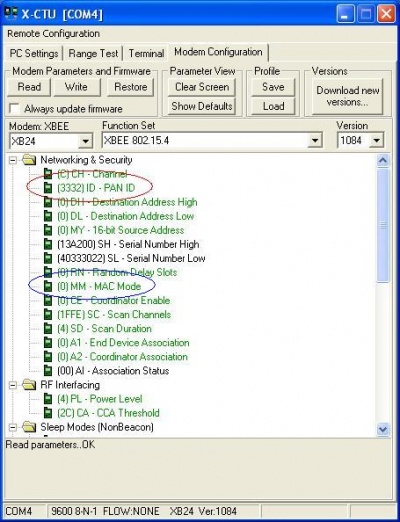
- 7. Click the Read button. In a few moments, the screen will display multiple configuration items.
- 8. Only four items need changing: PAN ID, MAC Mode, Interface Data Rate and Packetization Timeout (scroll down the XCTU screen to view more settings).
- PAN ID: this is akin to a "domain" for a computer network, but for XBee, the ID is numerical instead of text. The default is 3332 for all XBee modules, but you can change it to a different number if you wish or if another XBee network is in use nearby. Note that only modules with the same PAN ID can communicate with one another. (See PAN ID concept notes below)
- MAC Mode: choose option 1 – 802.15.4 No ACKS. While all the modes function, this setting is the fastest for streaming data.
- Interface Data Rate: this is the speed at which the XBee will communicate with the Renard SS controllers. Set this to 57600 for best performance. While the maximum setting for both a Renard and an XBee is 115,200, XBee radios are designed to provide up to 80kbps streaming throughput; setting to 115,200 may cause erratic behavior.
- Packetization Timeout: set to zero (the default is 3). A zero setting makes the XBee perform faster.
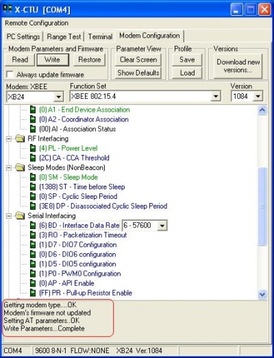
- 9. When changes are complete, click the Write button near the top of the XCTU screen to save the changes to the XBee’s internal memory. A progress bar will appear and in a few moments, the completion message will appear such as the one in the lower left corner of this screen:
- 10. Because the XBee's communication parameters have changed, you can return to the first screen (steps #3-4 above), change the communication parameters to 57,600 baud, requery the modem and reconnect to it to check your settings.
Setting an XBee Module's Address
- Connecting to all XBee modules simultaneously is easy: just set the PANIDs on each module to the same number. However, if you want to create a daisy chain network architecture where one module transmits to a specific next module, and so forth, you need to go a little further.
- If you have two modules on each Ren-W board (a real luxury because of the added expense!), you can simply set the PANIDs of the two modules that will communicate with one another to the same PANID. See the "Point to Point" broadcasting example on the Ren-W Configuration Concepts page.
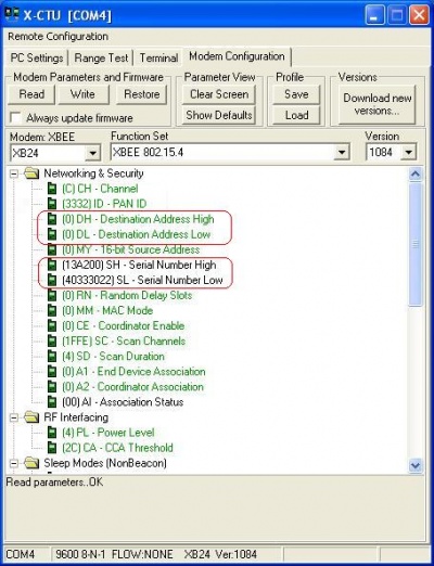
- However, in Alternate PTP mode with only ONE XBee module installed on a Ren-W board (XBee module in the TX position and jumper on JP5) XBee addressing is used instead. With addressing, you have multiple options:
- Notice the 16-bit source address option in the above window. You can insert a numerical address of your choosing here, such as 1001, 1002, 1003, etc. and leave the PANID the same for all modules. To create a daisy chain network, you would assign the "destination address high" of the first module to be the 16-bit address of the next module. You would continue this logic throughout your XBee network by assiging a specific 16-bit address to each module and then assigning the desired destination addresses.
- Instead of assigning a 16-bit source address of your own, you may choose to use the predefined serial numbers instead. If you do, be sure to use both the serial number high and serial number low of the receiving module as the transmitting module's destination address high and destination address low. Using the serial numbers makes the network the most secure it can possibly be because no two XBee modules are manufactured with the same serial number high and low.
- TIP #1: Be sure to write each radio's 16-bit address and it's assigned destination address on a piece of tape and either tape it to the XBee itself or to your enclosure so you know which radio transmits to which.
- TIP #2: By defining two or more XBee modules with the same 16-bit address, you can control them simultaneously from only one radio. However, don't assign multiple XBees to the same destination address or the receiving XBee may receive different commands from two different sources; the result will likely be confusion.
