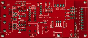
Ren4Flood
Ren4Flood Construction Manual
Please see the standard Disclaimers
What is the Ren4Flood?
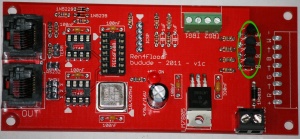
The Ren4Flood is a four channel controller primarily aimed at controlling an RGB+W LED flood such as the MightyMini, Rainbow Flood (RGB only) or the DIYC Flood. It uses the existing Renard architecture and code which has been modified to only consume four channels versus the normal eight that a Renard uses per PIC. The logic/control/communication portion of the circuit comes straight from the RenardSS series of controllers so much of the credit goes to Wayne James and of course Phil Short for their contributions. The output section is taken from the Ren48LSD but reduced to only four channels. One minor difference on the RS-485 interface is that jumpers have been added to bypass the input directly to the output creating a non-regenerated "THRU" port instead of the more common output port on the RenSS series. This allows you to use static node addressing without affecting other nodes further up/down the line.
The other significant difference with the Ren4Flood is that it employs two input trigger ports. While this is not completely defined at the moment, the idea is of at least two different scenarios. The first allowing the installation of a switch to be mounted to the flood enclosure and simply turning on all of the LEDs to create a bright flood to be used during setup or off-season. The other scenario is using a trigger for security reasons. The input would be connected to some type of N/O switches and closing the switch would trigger the board to perform some type of light effect to scare off and/or alert you to this. Additional code could be used to monitor the input for data and if after a particular time period passes with no traffic (say 15 minutes), a light pattern would start for a set length of time to create simple mood/background lighting after the show completes.
How does the Ren4Flood work?
As mentioned before, the Ren4Flood uses the same architecture for the logic portions of the board from the RenardSS series of boards. Sequence information is passed from a PC running Vixen or other sequencing program via an RS-232 or RS-485/DMX interface. The ST485 chips receive this information and turn into standard TTL logic levels that the PIC can understand. The PIC reads in the data and if it determines that the information corresponds to itself, it updates the dimming levels of all 4 channels. It removes this information from the stream and feeds the rest out to the other ST485 chip which translates it to RS-485 levels for the next controller in the line. It is important to realize that the information is removed from the stream and that the resultant leftover stream will have all of the data offset by the 4 channels of information used by the Ren4Flood. For example, if you have two Ren4Flood, on Vixen you would configure a single Renard/DMX plug-in with 8 channels. The first Ren4Flood consumes the first 4 channels of information leaving only 4 channels on it's outputs. The second Ren4Flood will see this incoming data as controller #1 again and assume the data is for it. This is very much different than standard hard/soft-coded DMX or LOR devices that use a set address yet still pass on the entire stream to the next controller on the line. There are advantages and disadvantages to either approach - but you should be aware of this when combining normal DMX devices before/after a Ren4Flood (or any Renard controller running DMX code).
The Ren4Flood has a jumper to bypass this however and can pass the data straight from the input to the output plug. This means you will need to set the hardware address by programming the PIC with different addresses on each Ren4Flood controller.
The PICs receive the data on pin 5 and after consuming their 4 channels of data, forward the rest out of pin 6 of the PIC which in turn goes to the next controller if you have one attached as mentioned above.
The board requires a 12-24vdc supply which is converted to +5v for the logic portion of the controller but is also fed directly out to the outputs via the transistors.
The Ren4Flood uses sourced outputs and not sinked outputs like the RenardSS controllers. Why is this? Because the PIC needs to turn on a transistor and to do this, it supplies 5v on it's output which turns on the transistor (via a resistor to limit the current) which allows current to flow from the collector to the emitter of the transistor. The emitter is directly connected to ground so basically, the transistor sinks the current from the LEDs (or whatever you have attached to the output) to ground. The positive voltage from the DC power supply connects directly to the device you have attached and this completes the circuit.
Revision History
The v1c version is currently the only version of the Ren4Flood in production.
Ren4Flood (v1c) Parts
In addition to the PCB, you will need the following components:
| Mouser BOM | ||
| Mouser PN | Description | Qty |
| 579-PIC16F688-I/P | Microcontrollers (MCU) 7KB 256 RAM 12 I/O | 1 |
| 571-1-390261-3 | IC & Component Sockets 14P ECONOMY TIN | 1 |
| 511-ST485BN | Buffers & Line Drivers Hi-Spd Lo Pwr Trans | 2 |
| 571-1-390261-2 | IC & Component Sockets 8P ECONOMY TIN | 2 |
| 520-TCH1843-X | ECS-2100AX-18.432MHZ | 1 |
| 863-MPS2222AG | Bipolar Transistors 600mA 75V NPN | 4 |
| 78-1N5239B | Zener Diodes 9.1 Volt 0.5 Watt | 1 |
| 78-1N5229B | Zener Diodes 4.3 Volt 0.5 Watt | 1 |
| 863-1N5819G | Schottky (Diodes & Rectifiers) 1A 40V | 1 |
| 512-LM7805CT | Linear Regulators - Standard 1A Pos Vol Reg | 1 |
| 532-577102B00 | Heatsinks TO-220 HORIZ/VERT SLIM CHANNEL STYLE | 1 |
| 604-WP7113ID | Standard LED - Through Hole HI EFF RED DIFFUSED | 1 |
| 581-SA105E104MAR | Multilayer Ceramic Capacitors (MLCC) - Leaded 50volts 0.1uF 20% Z5U | 5 |
| 647-UHE1C471MPD | Aluminum Electrolytic Capacitors - Leaded 16volts 470uF 105c 8x15 3.5LS | 1 |
| 581-SA105E224MAR | Multilayer Ceramic Capacitors (MLCC) - Leaded 50volts 0.22uF 20% Z5U | 1 |
| 581-SA305E105MAR | Multilayer Ceramic Capacitors (MLCC) - Leaded 50volts 1uF 20% Z5U | 2 |
| 299-680-RC | Carbon Film Resistors 680ohms | 1 |
| 299-120-RC | Carbon Film Resistors 120ohms | 1 |
| 299-27K-RC | Carbon Film Resistors 27Kohms | 2 |
| 299-1K-RC | Carbon Film Resistors 1.0Kohms | 4 |
| 299-470-RC | Carbon Film Resistors 470ohms | 4 |
| 299-10K-RC | Carbon Film Resistors 10Kohms | 3 |
| 571-5556416-1 | Telecom & Ethernet Connectors 8 PCB TOP ENTRY | 2 |
| 571-7969492 | Terminal Blocks 5.08MM VERTICAL 2P wire protector | 1 |
| 651-1727078 | Fixed Terminal Blocks 8P 3.81mm 90DEG | 1 |
| 651-1727036 | Fixed Terminal Blocks 4P 3.81mm 90DEG | 1 |
| 538-22-28-4056 | Headers & Wire Housings 5CKT VERT HDR | 1 |
| 538-70287-1001 | Headers & Wire Housings C-GRID .100" 2X03P VT HDR | 1 |
| 571-5-146281-2 | Headers & Wire Housings 2 P HEADER GOLD 30u single row | 2 |
| 649-65474-002LF | Headers & Wire Housings SHUNT TIN | 3 |
Click here for Mouser Direct Project BOM
Most of the components are not overly critical and some can be omitted in certain cases.
The BOM is available from DIYLEDExpress.com
Building the Ren4Flood
The Ren4Flood requires a modest bit of soldering so take your time and ensure you install the components in the correct orientation when required. Start by sorting the components by type and values. Look over the PCB before starting noting the location of the various components. Follow the standard procedure of installing the lowest profile parts first and ending up with the tallest. Begin by inspecting the PCBs to look for any defects such as cracks or breaks. The holes on the board should be open on both sides. Then inspect and sort out the various parts for the board.
1. Install the three 10k resistors near top center of the board
2. Install the four 1k resistors two near the top 485 chip and two near the middle of the board
3. Install the two 27k resistors near the top 485 chip
4. Install the one 120 resistor near the top 485 chip
5. Install the one 680 resistor near the LED in the middle of the board
6. Install the 1N5229 diode above the top 485 chip – note the correct orientation - the band on the diode goes towards the right side of the board
7. Install the 1N5239 diode above the top 485 chip – note the correct orientation - the band on the diode goes towards the left side of the board
8. Install the four 470 ohm resistors near the right side of the board
9. Install the five 0.1uf decoupling capacitors near the IC sockets, oscillator and near the voltage regulator. Note that the silkscreen says 100nF.
10. Install the one 0.33uf capacitor to the right of the voltage regulator. Note that the silkscreen says 330nF. The BOM lists a 0.22uf capacitor, either a 0.22uf or a 0.33uf can be used.
11. Install the two 1.0uf capacitors and near the ICSP header. Note that the silkscreen says "1uF".
12. Install the one 14-pin PIC chip socket and the two 8-pin 485 chip sockets - note the correct orientation with the socket notch in the same direction as the silk screen.
13. Install the 18.432MHz oscillator – note the correct orientation - the package has one square corner (and a dot) and that goes into the square hole on the board
14. Install the two 2-pin headers on the left side of the board in the term and rs232 holes
15. Install the one 2x3-pin header to the left of the bottom rs485 chip
16. Install the one 5-pin header in the top center of the board int the holes marked ICSP
17. Install the LED – note correct orientation - the flat side of the LED faces to the left. The longer leg of the LED goes in the hole to the right.
18. Install the one 2-terminal DC input terminal blocks – note correct orientation - have the side where the power wires will be inserted facing the bottom of the board
19. Install the one 4-terminal trigger terminal block on the top right of the board.
20. Install the one 8-terminal flood terminal block to the right side of the board.
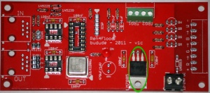
21. Install the LM7805 regulator - note correct orientation - pin 1 is denoted by the dot on the package and the board. Mount the heat sink to the device and use a small amount of heat sink compound
22. Install the one 1N5819 diode near the voltage regulator – note the correct orientation - the diode has the band on the diode facing towards the top of the board. If you are using 12v for the supply, you may want to install a wire jumper here instead so that the additional voltage drop does not effect the brightness as much.
23. Install the 470uF/16v capacitor – note correct orientation - the capacitor has a stripe on the side denoting the negative leg that goes in the hole near the "-"mark on the board.
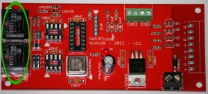
24. Install the two RJ45 jacks – note that side-entry jacks can be substituted
25. Install the 4 transistors – note the correct orientation – the flat side of the package faces towards the bottom of the board.
Congratulations! That completes the construction of the Ren4Flood!
Connecting the Ren4Flood to the DIYC Flood
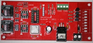
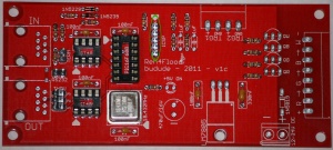
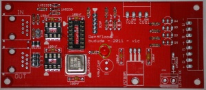
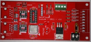
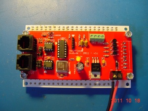
Here is the view from the top of the Ren4Flood
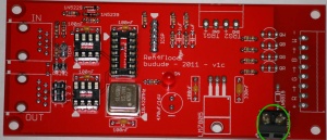
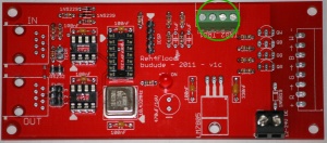
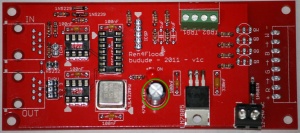
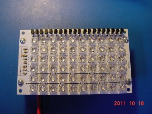
Here is the view from the other side with the DIYC Flood
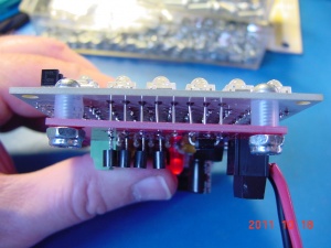
Run solid wire completely through the boards and solder both ends. Use 6-32 screws with locking nuts and pieces of ice-maker tubing as spacers.
Initial Testing
The first thing you will want to do in any PCB construction project is to double check that you have all components installed and in the proper orientation. You will then want to inspect the board for any cold/bridged solder joints. Take your time with this step and go over each and every joint.
If you have any of the IC's installed - remove them now. Connect your power supply to the “DC IN” - it supplies power to controller portion of the board as well as the outputs. Turn on the supply and verify the power LED lights up. Verify you have 5v between pins 1 and 14 on the PIC socket as well as between pins 5 and 8 on the 485 chip sockets. Install all of the IC's if this passes. The PIC goes in the 14 pin socket with the notch facing the top of the board. The two 485 chips go in the 8 pin sockets on the left side of the board and the notches face to the left.
Programming the PIC controllers
The Ren4Flood does not supply or use a ZeroCross input and therefore the Renard firmware (either Renard or DMX protocol) must be configured for DC/PWM operation. In addition, if you are using the DMX firmware, you may want to set the initial starting address but generally, this can be left at '1' for all PICs since the code is self-addressing. Also – like the ULN2803 drivers, the transistors invert the output so the firmware uses positive outputs.
Renard Protocol
Use standard Ren48LSD/Serial code - it will require you to skip channels 1-4 in your sequencer as the code still consumes 8 channels. Obtain the standard Renard firmware for 16F688 PICs here. If you are using a newer 16F1825 PIC, you can find compatible firmware on the forums File section.
Make the following changes:
#define PWM_build 1 – change from '0'
#define DC_build 1 – change from '0'
#define CTR_LOCKOUT 1 – change from '15'
;#define OUTPUT_NEGATIVE_TRUE – comment this out
Compile the code into hex code and program the PIC. A standard version of the code with the settings above has been compiled already for you in the File Library available here.
Note that when using the standard Ren48LSD/Serial code, that you need to account for eight channels even though there are only four used on the Ren4Flood. Channels 1-4 are not used and channels 5-8 are for the four outputs.
There is no trigger code written for the Ren4Flood at this time so the trigger inputs are not functional yet. This functionality may be added at a later time.
Renard-DMX Protocol
Obtain the Ren4Flood firmware from here:
If you want to change the DMX starting address then alter it below.
#define DMX_START_ADDRESS 1
Compile the code into hex code and program the PIC with the same code (unless using a starting address). A standard version of the code with the settings above has been compiled already for you in the File Library available here.
Whichever firmware you choose, install the flashed PIC into the socket noting the correct orientation. Also install the two 485 chips into their sockets noting the correct orientation. You are now ready for final testing.
There is no trigger code written for the Ren4Flood at this time so the trigger inputs are not functional yet. This functionality will be added at a later time.
Final Testing
I chose not to design in the diagnostic LEDs as those used on the RenSS series of controllers. The design is fairly straight-forward and as long as you are sure of the voltage inputs and the PICs are flashed properly you should not have any issues if your soldering is good.
If you are using RS232, you should install the shunt on the "RS232" header which shorts pin 5 of the RJ45-IN connector to ground for proper RS232 operation. The wiring is the same as the RenardSS series so you can follow the cabling requiremnents for that.
As the Renard controller variations do not use bussed DMX it's not critical to install the DMX termination shunt if you are only using Renard controllers. This is because they are using point-to-point configurations. However - if this particular controller is at the end of a line of other normal (bussed) DMX devices, you should install the shunt to properly terminate the bus.
Connect the Ren4Flood to your PC using standard wiring practices as on the Wiki for other Renard controllers. Develop a Vixen sequence to turn on/off each channel one-by-one using the appropriate Renard/DMX plug-in. With the sequence running, measure the output of each terminal block pair and ensure the voltage swings from 0 to DC IN.
TroubleShooting
So - you've built your new Ren4Flood, connected it up to your computer and tried a quick sequence and nothing happens! There are several checks to perform in order:
Visual Inspection
The very first step involves a close visual inspection of the board. Double check that you have the correct component in the correct location and in the correct orientation. Look at every single solder connection and if some are not shiny or look suspect - reflow them to be sure.
Power
Measure across pins 1 and 14 on the PIC socket - it should read 5v
Measure across pins 5 and 8 on both RS-485 sockets - it should read 5v
If you do not measure 5v and you are using the regulator, then ensure you are providing at least 7.5vdc (and up to 24vdc) into the terminal block from your supply. If that's OK, then inspect the soldering all around the regulator and filter capacitors on the board. Ensure the filter capacitor and regulator were installed with the correct orientation.
PIC Programming
Reflash your PIC with the .hex file from this Wiki page or the File Library - perform a 'Verify' to be sure it's not blank
Clocking
With the PIC installed, measure the voltage from pin 14 (gnd) to pin 2 (OSC) on the PIC - it should not be stuck at 0 or 5v (probably close to 3.5v). If it is then you probably have a soldering issue, the oscillator was installed with the incorrect orientation or the oscillator is bad. There should be 5v between the upper left and lower right pins on the oscillator.
Another possible reason for seeing close to 5v on pin 2 is that the PIC has been programmed properly. This is due to no loading of the output from the oscillator. Before replacing the oscillator, re-verify that the PIC has been programmed.
Communications
From Vixen, ensure you have the appropriate plug-in selected and configured. If you are using Renard/Serial code, you should have the "Renard Dimmer (modified)" selected using Protocol Version 1 and the correct COM port selected for your serial port. Ensure the baud rate is 57600 (if using the standard image), 8-bits, no parity, 1 stop bit and that it matches the port settings in the Windows Control Panel (Device Manager) as well. Ensure your cabling is correct from the Wiki documentation for Renard (it is the same as the RenSS series). Ensure the "RS232" jumper is ON and that the "TERM" jumper is OFF.
If you are using Renard/DMX code, you should have either the "Enttec Open DMX" or "Enttec DMX USB Pro" plug-in selected (unless you are using E1.31 which is beyond this document). Ensure your DMX dongle is seen as a COM port (unplug/plug in to be sure while Vixen is not up) and the plug-in is configured to match the port number. The baud rate settings are not used for DMX (it's always 250Kbps). If using the Enttec Open dongle, you need to configure the DMX Add-In as well so that the data is streamed to the device.Ensure your cabling is correct from the Wiki documentation for Renard (it is the same as the RenSS series). Ensure the "RS232" jumper is OFF. The "TERM" jumper will probably make no difference whether it's on or off but you can try both ways to see if it makes any difference.
Note that it's not really within the scope of this document to troubleshoot Vixen/dongle/cabling issues - please go through some of the Wiki documentation and if at all possible, try to confirm on a working piece of equipment before troubleshooting something that isn't broken to begin with. It's assumed at this point that to the best of your knowledge that everything up to the "IN" jack is in working order.
Configure a short Vixen sequence with a slow on/off sequence for each channel - 1 second on, 1 second off. Alternate the odd channels so that they are the opposite polarity of the even channels. In other words, when channel 1 is ON, channel 2 is OFF or when channel 2 is ON, channel 1 is off. Create a 4-channel sequence in this fashion so you can test all channels at once. With the sequence running, measure the outputs of the PIC at pins 10, 9, 8 and 7. You should see each pin alternate from 0v to 5v once a second matching the sequence. If this is not the case, then sequencing data is not being received by the PIC(s).
Measure the voltage at pin 5 on PIC with the same sequence running (from ground). it should be alternating between 0v and 5v and not be stuck at one or the other. If it appears stuck, then inspect the "IN" RS-485 chip (and the entire path from it to pin 5 on the PIC) and ensure there are no bent pins (including the RJ45 jack itself), cold solder joints. Swap the two RS485 chips to see if that resolves the issue.
If the problem is with a daisy-chained controller FROM this Ren4Flood, then inspect the RS-485 "OUT" chip closely for bent pins, solder issues, etc. Check the output RJ45 jack for crossed pins. Swap the RS-485 chips to see if that helps. Note that ALL output from the Ren4Flood is at RS-485 levels so the daisy-chained controller should not have the RS-232 jumper enabled.
Output Drivers
It's assumed at this point that you have checked that a sequence can drive the PIC outputs properly between 0 and 5v OK. With the PIC(s) removed and power on, connect a known good device (flood, RGB strip, etc) to the output socket(s) in question.
Use a piece of hookup wire and connect the wire from pin 1 to the following pins:
- Pin 10 - channel 1
- Pin 9 - channel 2
- Pin 8 - channel 3
- Pin 7 - channel 4
After connecting the wire to the output pins, the device should turn on. If it does not, then it's possible the output driver (transistor) is bad. Check the path from the PIC output pin you are testing through the 470 ohm resistor and to the base of the transistor in question. The nomenclature (name) of the transistor matches the channel number so "Q2" is for channel 2. Replacements may have been included with your kit or you can get them at RadioShack - most MPS2222a, PN2222A or 2N3904 types can be subsituted. If you have multiple transistors bad, then you should investigate how this happened before replacing the transistors since there's a good chance they will simply blow again.
FAQ
What are the jumper settings for the board?
There are three jumper settings on the Ren4Flood pcb.
1) The first jumper is the TERM jumper. You may need to connect the shunt across the two pins if this is the last device in a string of DMX devices.
2) The second jumper is the RS232 jumper. You may need to connect the shunt across the two pins if you are sending data to the board using RS232 signaling.
3) The Third jumper is the THRU jumper. This is a 2x3 header. For "normal" Renard operation, there should be a pair of jumpers across both 1&2 (they go vertically). For "THRU" they should go across 2&3. Basically this jumpers pins 4&5 from the IN connector directly to the OUT connector. If you use the THRU connection using the standard Ren48LSD code, it will not be an issue since ALL data is bypassed across the connector. You will need to set the starting address on each PIC however.
Can you program the pic while it is on the board?
Yes, by using the ICSP header connected to your PIC2 or PIC3 programmer you can program the PIC while it is on the board. Please make sure to note the orientation of pin 1 of the ICSP header (marked by the arrow at the top).
Schematic
Here is the schematic drawing for the Ren4Flood v1c in PDF format Media:Ren4Flood-v1c.pdf
PCB
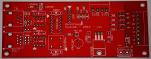
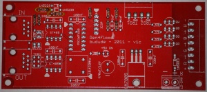
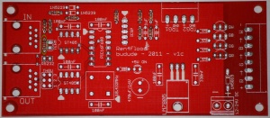
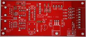
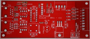
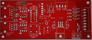
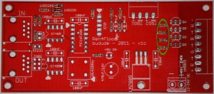
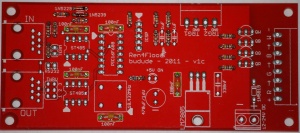
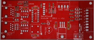
The PCBs for the Ren4Flood were designed by Brian Ullmark (budude). The PCB is 4.75" x 2.1". The PCB is available from DIYLEDExpress.com
