Setting up Channels: Difference between revisions
No edit summary |
No edit summary |
||
| Line 2: | Line 2: | ||
''The following tutorial was based on Version 11F''<br /> | ''The following tutorial was based on Version 11F''<br /> | ||
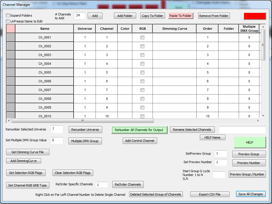
Click directly | In Figure 1-8.3 the channel names are now Ch_0001, through Ch_0024. We are going to change the names to reflect their use. <br /> | ||
In this example we will have two trees: Tree_1 and Tree_2. Each tree will have 3 outputs; red, green and blue. | |||
Figure 1-8.3.<br /> | |||
[[File:Figure1-8.3_v11.png]] | |||
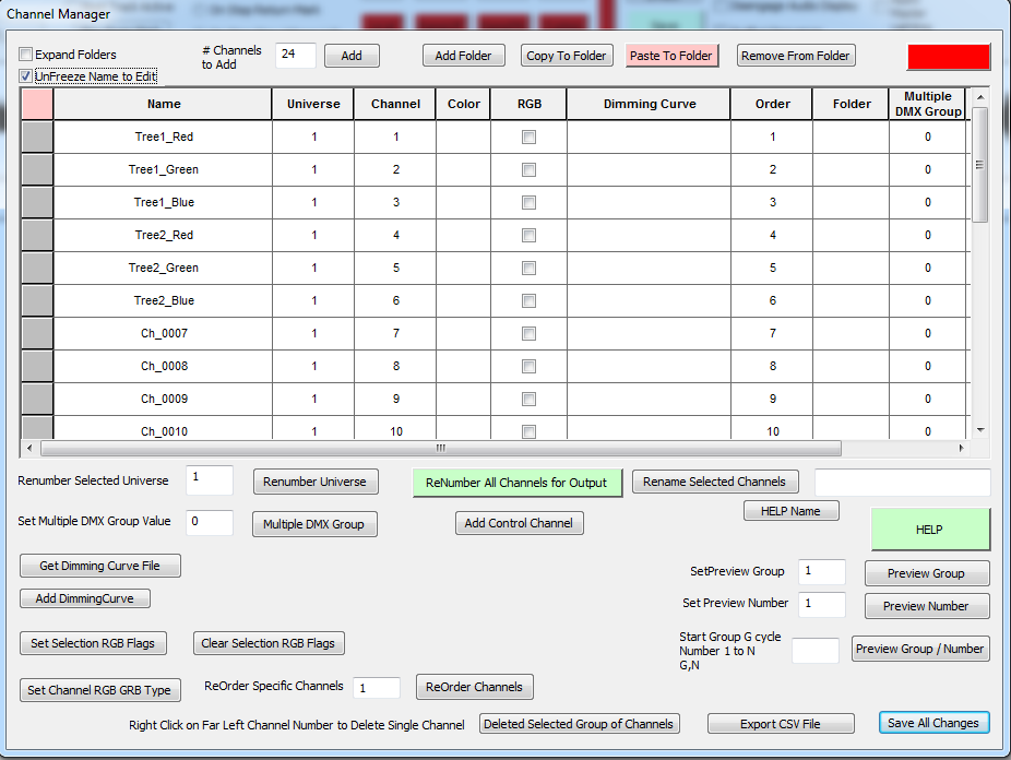
To rename the outputs first Click the "UnFreeze Name to Edit" check box above the Channel name column. This allows you to edit the channel names directly. After UnFreezing the name column the channel window may shift to the right. If so you just need to move the lower scroll bar back to the left to see the channel names again. Now all you have to do is click in each channel name you want to change and type in what you want. You can use cut and paste from one cell to another. There are other ways to rename channels which are much easier for large numbers of channels but for this example the easiest way is to directly rename them. Rename them as shown in the example in Figure 1-8.5. | |||
Figure 1-8.5.<br /> | |||
[[File:[[File:Figure1-8.5_v11.png]] | |||
The color was chosen for each output next. The color will be used in the simulation. To set the color for an output you must choose the desired color in the upper right of the screen (see Figure 1-9). In this example Red was chosen. Next you must Click on the '''Active Color Selection''' check box right next to the color box in the upper right corner. At this point you have chosen the desired color and checked the '''Active Color Selection''' check box. | The color was chosen for each output next. The color will be used in the simulation. To set the color for an output you must choose the desired color in the upper right of the screen (see Figure 1-9). In this example Red was chosen. Next you must Click on the '''Active Color Selection''' check box right next to the color box in the upper right corner. At this point you have chosen the desired color and checked the '''Active Color Selection''' check box. | ||
| Line 10: | Line 23: | ||
Next right click in the desired channel row '''Color''' box and it will change to the chosen color (see Figure 1-9). | Next right click in the desired channel row '''Color''' box and it will change to the chosen color (see Figure 1-9). | ||
Revision as of 06:25, 31 January 2013
Back to: HLS Getting Started Manual
The following tutorial was based on Version 11F
In Figure 1-8.3 the channel names are now Ch_0001, through Ch_0024. We are going to change the names to reflect their use.
In this example we will have two trees: Tree_1 and Tree_2. Each tree will have 3 outputs; red, green and blue.
To rename the outputs first Click the "UnFreeze Name to Edit" check box above the Channel name column. This allows you to edit the channel names directly. After UnFreezing the name column the channel window may shift to the right. If so you just need to move the lower scroll bar back to the left to see the channel names again. Now all you have to do is click in each channel name you want to change and type in what you want. You can use cut and paste from one cell to another. There are other ways to rename channels which are much easier for large numbers of channels but for this example the easiest way is to directly rename them. Rename them as shown in the example in Figure 1-8.5.
The color was chosen for each output next. The color will be used in the simulation. To set the color for an output you must choose the desired color in the upper right of the screen (see Figure 1-9). In this example Red was chosen. Next you must Click on the Active Color Selection check box right next to the color box in the upper right corner. At this point you have chosen the desired color and checked the Active Color Selection check box.
Next right click in the desired channel row Color box and it will change to the chosen color (see Figure 1-9).
The same process was followed to assign the green and blue colors to outputs. Note that this screen can also be used to renumber universes and or renumber output channels. We are now done with this screen, click on the Save All Changes button.
Next: Configuring Groups

