Simple Renard 32 Combo: Difference between revisions
| (12 intermediate revisions by 5 users not shown) | |||
| Line 1: | Line 1: | ||
=Simple Renard 32 Combo - 32 Channel Controller= | =Simple Renard 32 Combo - 32 Channel Controller Version 1 Board= | ||
[[File:Sr32c_Step9.jpg|500px]]<br/> | [[File:Sr32c_Step9.jpg|500px]]<br/> | ||
| Line 11: | Line 8: | ||
The standard disclaimers pertaining to the information contained on this wiki page are listed [[Disclaimers | here.]]<br/> | The standard disclaimers pertaining to the information contained on this wiki page are listed [[Disclaimers | here.]]<br/> | ||
== '''IMPORTANT NOTE: THIS BOARD IS NO LONGER IN PRODUCTION!''' == | |||
==What is the Simple Renard 32 Combo?== | ==What is the Simple Renard 32 Combo?== | ||
| Line 74: | Line 73: | ||
[http://www.mouser.com:80/ProjectManager/ProjectDetail.aspx?AccessID=404d2dcb3c Click Here for Mouser Direct Project BOM] | [http://www.mouser.com:80/ProjectManager/ProjectDetail.aspx?AccessID=404d2dcb3c Click Here for Mouser Direct Project BOM] | ||
The Kit is available at [http://www.diyledexpress.com/index.php?main_page=product_info&cPath=17&products_id=101 DIYLEDExpress.com] | |||
===Housing=== | ===Housing=== | ||
The Simple Renard 32 Combo was designed to fit in the [http://www.aflglobal.com/cmspages/bluekey/getfile.aspx?aliaspath=/productlist/Product-Lines/Optical-Connectivity---Apparatus/CableGuard-500-Coax-Demarcation-Enclosure/doc/CG-500-Coax-Demarcation-Enclosure CG-500 Demarcation Enclosure] available from numerous vendors including [http://wlcventures.com/zencart/index.php?main_page=index&cPath=1| www.wlcventures.com]<br/> | The Simple Renard 32 Combo was designed to fit in the [http://www.aflglobal.com/cmspages/bluekey/getfile.aspx?aliaspath=/productlist/Product-Lines/Optical-Connectivity---Apparatus/CableGuard-500-Coax-Demarcation-Enclosure/doc/CG-500-Coax-Demarcation-Enclosure CG-500 Demarcation Enclosure] available from numerous vendors including [http://www.diyledexpress.com/index.php?main_page=index&cPath=16 www.diyledexpress.com] and [http://wlcventures.com/zencart/index.php?main_page=index&cPath=1| www.wlcventures.com]<br/> | ||
=Building the Simple Renard 32 Combo= | =Building the Simple Renard 32 Combo= | ||
| Line 156: | Line 157: | ||
==Mounting in Housing== | ==Mounting in Housing== | ||
The Simple Renard 32 Combo was designed to be mounted in any convenient enclosure, however it will fit nicely in the CG-500 enclosure sold by various vendors including [http://www.diyledexpress.com/index.php?main_page=product_info&cPath=16&products_id=105 DIYLEDEXPRESS.COM] or [http://wlcventures.com/zencart/index.php?main_page=product_info&cPath=1&products_id=18 WLCVENTURES.COM]. <br/> | |||
=Jumper Settings / Headers= | =Jumper Settings / Headers= | ||
| Line 190: | Line 191: | ||
=Power Requirements= | =Power Requirements= | ||
The board requires a 9-12 vac power supply. It will not work with a DC power supply. A 9-12vac wall wart power supply can be connected to the power input terminals of the board. | The board requires a 9-12 vac power supply. It will not work with a DC power supply. A 9-12vac wall wart power supply can be connected to the power input terminals of the board. | ||
Since the board does not have a fuse, it it recommended to add an in-line 1A fuse to the power input. | |||
= Connecting up the Simple Renard 32 Combo= | = Connecting up the Simple Renard 32 Combo= | ||
| Line 245: | Line 248: | ||
=Firmware= | =Firmware= | ||
The Simple Renard 32 Combo makes use of a different PIC then the usual PIC found in most Renard devices. '''The Simple Renard 32Combo does not use the default Renard firm. You must make use of the special firmware listed below to program your Simple Renard 32 Combo.''' The Simple Renard 32 Combo firmware runs Renard protocol | The Simple Renard 32 Combo makes use of a different PIC then the usual PIC found in most Renard devices. '''The Simple Renard 32Combo does not use the default Renard firm. You must make use of the special firmware listed below to program your Simple Renard 32 Combo.''' The Simple Renard 32 Combo firmware runs Renard protocol and is setup with start addressing to run with dirknerkle's RenW wireless boards. A DMX version is currently being tested and should be available sometime in May 2012. | ||
The Simple Renard 32 Combo has one version of the software available. | The Simple Renard 32 Combo has one version of the software available. | ||
| Line 262: | Line 265: | ||
===Downloads=== | ===Downloads=== | ||
Simple Renard 32 Combo Firmware (32 channels) [http://doityourselfchristmas.com/forums/dynamics/showentry.php?e=106&catid=6.htm SR 32 Combo] | Simple Renard 32 Combo Firmware (32 channels) [http://doityourselfchristmas.com/forums/dynamics/showentry.php?e=106&catid=6.htm SR 32 Combo]<br/> | ||
Simple Renard 32 Combo Beta DMX Firmware (32 channels)[http://doityourselfchristmas.com/forums/dynamics/showentry.php?e=191&catid=6.htm SR 32 Combo DMX]<br/> | |||
=Schematic= | =Schematic= | ||
| Line 272: | Line 276: | ||
PCBs are available from [http://n7xg.net/diycprojects.html N7XG (Dean)] | PCBs are available from [http://n7xg.net/diycprojects.html N7XG (Dean)] | ||
or kits are available at [http://www.diyledexpress.com/ diyledexpress] | |||
=Design Options= | =Design Options= | ||
Latest revision as of 21:36, 31 May 2013
Simple Renard 32 Combo - 32 Channel Controller Version 1 Board
Disclaimers
The standard disclaimers pertaining to the information contained on this wiki page are listed here.
IMPORTANT NOTE: THIS BOARD IS NO LONGER IN PRODUCTION!
What is the Simple Renard 32 Combo?
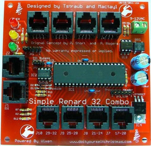
The Simple Renard 32 combo is a low cost 32 channel controller designed to drive either ACSSRs or DCSSRs which switch their loads close to the item being controlled. Unlike other Renard designs like the Renard 64XC, the Simple Renard 32 Combo makes use of a different PIC, the PIC18F4520. This PIC allows 32 chanels per PIC to be controlled compared to the usual 8 channels per PIC (16F688) used in most Renard designs. This allows a smaller board and lower total cost.
The Simple Renard 32 Combo controller is used to control loads in a "star" type system. This means, that the main controller stays in a central location while the SSRs are on the tips of the "spokes". The real savings in this layout is in the power cables. Most of the channel power cables are very short. This system is very good for widely spaced display items with small groups of channels in one area like mini-trees.
The outputs of the Simple Renard 32 Combo are designed to be connected to SSRs which switch the actual loads. The Simple Renard 32 Combo can control DCSSrs like WJohn's DC SSR or Labrat's DCSSR Version 2.4. The Simple Renard 32 Combo can also control ACSSrs like Chris and John's SSRez or Dave's SSRneon
The board requires a good 9-12vac external power supply. An on board voltage regulator provides the necessary power for the PIC on the pcb.
The board was designed in the Fall of 2010 by Mactayl and tstraub, and based on original concepts by p.short, p.rogers.
How does the Simple Renard 32 Combo work?
The Simple Renard 32 Combo uses a similar architecture for the logic portions of the board as the RenardSS series of boards. Sequence information is passed from a PC running Vixen or other sequencing program via an RS-485 interface. The RS485 chip receives this information and turn into standard TTL logic levels that the PIC can understand. The PIC reads in the data and if it determines that the information corresponds to itself, it updates the dimming levels of all 32 channels. It removes this information from the stream and feeds the rest out to the RS485 chip which translates it to RS-485 levels for the next controller in the line. It is important to realize that the information is removed from the stream and that the resultant leftover stream will have all of the data offset by the 32 channels of information used by the Simple Renard 32 Combo. For example, if you have two Simple Renard 32 Combo, on Vixen you would configure a single Renard plug-in with 64 channels. The first Simple Renard 32 Combo consumes the first 32 channels of information leaving only 32 channels on it's outputs. The second Renard 32 Combo will see this incoming data as controller #1 again and assume the data is for it. This is very much different than standard hard/soft-coded DMX or LOR devices that use a set address yet still pass on the entire stream to the next controller on the line.
The PIC in the Simple Renard 32 Combo uses the internal PIC oscillator.
So - now that the PIC has the updated dimming levels for all of it's channels, it enables each of its outputs using PWM or Pulse Width Modulation. It is important to grasp that the voltage levels are not controlled - it is the amount of time on and off that is varied within a small cycle of time for each update. It seems logical that to dim things you would just change the voltage from 12v to 9v for example. Instead, the voltage is on at the full 12v for x amount of time and then it is off (0v) for the y amount of time - it is not something in-between. The cycle time is controlled by the PIC in the case of the Simple Renard 32 Combo. The Simple Renard 32 Combo has a Zero-Cross (ZC) signal which is created by an opto-isolator attached to the AC line (via a transformer). The Zero Crossing (ZC) signal is the point at which the AC signal crosses zero volts. The ZC point needs to be known so that the triacs can be turned on/off at the correct time to achieve a dimming effect for AC loads. The Renard 32 Combo can use the ZC (for ACSSRs) to trigger the dimming or when the ZC chip is removed (for DCSSRs) the PIC basically makes up it's own timing but it closely resembles what is seen with normal ZC usage.
The output from the PIC is connected to either ACSSrs or DCSSRs to control loads.
Revision History
The Version v.1b is currently the most recent version of the Simple Renard 32 Combo in production.
Simple Renard 32 Combo Parts
In addition to the PCB, you will need the following components:
Mouser
| Part | Description | Mouser PN | Qty |
| P1 | Fixed Terminal Blocks 5.08MM VERTICAL 2P wire protector | 571-7969492 | 1 |
| BR1 | 4 pin Bridge rectifier 1amp dip | 625-DF02MA-E3 | 1 |
| C1 | 470uf 25V Electrolytic | 647-UVZ1E471MPD | 1 |
| C2 | 220uf 25V Electrolytic | 647-UVZ1E221MPD | 1 |
| C3,C4,C5 | Multilayer Ceramic Capacitors (MLCC) - Leaded 0.1uF 50volts Y5V +80-20% 2.5mm L/S | 81-RPEF51104Z2S2A03A | 3 |
| D2 | Zener Diodes 4.3 Volt 0.5 Watt) | 78-1N5229B | 1 |
| D1 | Zener Diodes 9.1 Volt 0.5 Watt) | 78-1N5239B | 1 |
| IC2 | RS-485 Interface IC LP Diff Pairs | 595-SN65LBC179P | 1 |
| IC3 | H11AA1 Zero Cross | 782-H11AA1 | 1 |
| IC4 | Linear Regulators - Standard 1A Pos Vol Reg | 512-LM7805CT | 1 |
| IC & Component Sockets 40P DUAL WIPE DIPSKT | 517-4840-6000-CP | 1 | |
| IC1 | Microcontrollers (MCU) 32KB 1536 RAM 36I/O | 579-PIC18F4520-I/P | 1 |
| ICSP | Headers & Wire Housings FLAT HEADER 6P Straight Post tinr | 571-6404526 | 1 |
| JP1 XBee header | Headers & Wire Housings FLAT HEADER 5P Straight Post tin | 571-640452-5 | 1 |
| Shunt for XBheader and PIC bypass | Headers & Wire Housings Mini Shunt .177" height | 737-MSC-G | 2 |
| J1-J10 | Ethernet & Telecom Connectors 8 PCB TOP ENTRY | 571-5556416-1 | 10 |
| Status Led | Standard LED - Through Hole YELLOW DIFFUSED | 78-TLHY5405 | 1 |
| Power Led | Standard LED - Through Hole RED DIFFUSED | 78-TLHR5410 | 1 |
| RX/TX Led | Standard LED - Through Hole GREEN DIFFUSED | 78-TLHG5401 | 1 |
| R1,R2,R8,R9,R10 | Carbon Film Resistors - Through Hole 1.0Kohms 0.05 | 291-1k-RC | 5 |
| R3,R5 | Carbon Film Resistors - Through Hole 330ohms 5% | 291-330-RC | 2 |
| R6 | Carbon Film Resistors - Through Hole 10Kohms 5% | 291-10k-RC | 1 |
| R7 | Carbon Film Resistors - Through Hole 120ohms 0.05 | 291-120-RC | 1 |
| R11,R12 | Carbon Film Resistors - Through Hole 27Kohms 5% | 291-27k-RC | 2 |
| PIC Bypass | Headers & Wire Housings NARROW FLT HDR 3P Straight Post | 571-3-644456-3 | 1 |
| IC & Component Sockets 8P DUAL WIPE DIPSKT | 517-4808-3004-CP | 1 | |
| IC & Component Sockets 6P DUAL WIPE DIPSKT | 571-1-390261-1 | 1 | |
| Wallwart 9-12 volts AC only | 507-XT1220 | 1 |
Click Here for Mouser Direct Project BOM
The Kit is available at DIYLEDExpress.com
Housing
The Simple Renard 32 Combo was designed to fit in the CG-500 Demarcation Enclosure available from numerous vendors including www.diyledexpress.com and www.wlcventures.com
Building the Simple Renard 32 Combo
Assembly
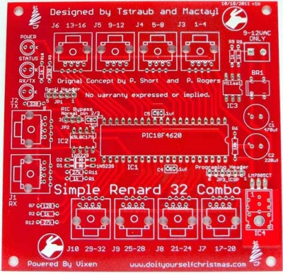
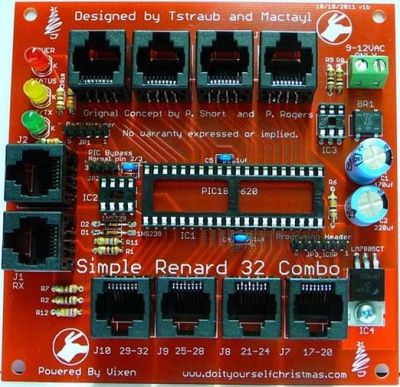
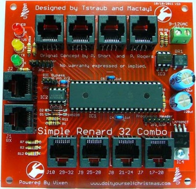
The Simple Renard 32 Combo is a simple device to assemble and test. It is easiest if you build the units by inserting the various components from smallest to tallest .
- Begin by inspecting the PCBs to look for any defects such as cracks or breaks. The holes on the board should be open on both sides. Then inspect and sort out the various parts for the board.
- Install the resistors:
- Install the 1K ohm resistors at locations R1,R2,R8,R9,R10. The resistor are not polarized, so they can go either way.
- Install the 330 ohm resistors at locations R3,R5. The resistor are not polarized, so they can go either way.
- Install the 10K ohm resistor at location R6. The resistor is not polarized, so it can go either way.
- Install the 120 ohm resistor at location R7. The resistor is not polarized, so it can go either way.
- Install the 27K ohm resistors at locations R11,R12. The resistor are not polarized, so they can go either way.
- Install the diodes:
- Install the 1N5239 diode at location D1. The diode is polarized and it can only go one way. The end with the band (cathode) goes towards the left side of the board.
- Install the 1N5229 diode at location D2. The diode is polarized and it can only go one way. The end with the band (cathode) goes towards the left side of the board.
- Install the IC sockets:
- Install the 6 pin socket at location IC3. The notch on the socket should face the right side of the board, matching the silkscreen image.
- Install the 8 pin socket at location IC2. The notch on the socket should face the right side of the board, matching the silkscreen image.
- Install the 40 pin socket at location IC1. The notch on the socket should face the right side of the board, matching the silkscreen image.
- Install the bridge rectifier at location BR1. The bridge rectified is polarized and it can only go one way. The side with the "+" and the "-" goes towards the bottom of the board and the side with the 2 "~" go towards teh top side of the board.
- Install the capacitors:
- Install the 470uf Electrolytic Capacitors at locations C1. The capacitor is polarized. The side of the capacitor will have a stripe on the negative side. The long lead is the positive side, and it goes in the hole marked with a +.
- Install the 220uf Electrolytic Capacitors at locations C2. The capacitor is polarized. The side of the capacitor will have a stripe on the negative side. The long lead is the positive side, and it goes in the hole marked with a +.
- Install the 0.1uf Ceramic Capacitors at locations C3,C4,C5. The capacitors are not polarized, so they can go either way.
- Install the light emitting diodes:
- Install the Red LED at the location marked Power. The LED is polarized. There is a flat side (cathode) that has a short lead and it faces towards the right side of the board.
- Install the Yellow LED at the location marked Status. The LED is polarized. There is a flat side (cathode) that has a short lead and it faces towards the right side of the board.
- Install the Green LED at the location marked RX/TX. The LED is polarized. There is a flat side (cathode) that has a short lead and it faces towards the right side of the board.
- Install the headers:
- Install the 5 pin header at location JP1 (RENW header). The short side of the header strip goes into the board.
- Install the 3 pin header at location JP2 (PIC bypass). The short side of the header strip goes into the board.
- Install the 6 pin header at location JP3 ICSP (PIC programming header). The short side of the header strip goes into the board.
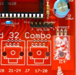
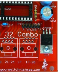
- Install the 5v linear regulator at location IC4. The voltage regulator is polarized and goes only one way. Gently bend the leads of the regulator at the location on the leads where it changes size down at a 90 degree angle towards the flat side of the regulator. Apply thermal grease to the flat heat sink side of the regulator and fasten it to the pcb using a #4 screw and nut.
- Install the RJ45 jacks at locations J1-10. Gently align the eight wires with the matching holes and snap the connector to the board. Solder the connector to the circuit board being careful to not short out the connectors.
- Install the 2 terminal strip1 at locations P1. The side where the wires enter under the screw should face the top of the board.
- Install the jumper shunts:
- Install the shunts on the headers according to the Header Settings listed below.
- Install the shunts on the headers according to the Header Settings listed below.
Initial Testing / Final Assembly
- The first thing you will want to do in any PCB construction project is to double check that you have all components installed and in the proper orientation. You will then want to inspect the board for any cold/bridged solder joints. Take your time with this step and go over each and every joint.
- If you have any of the IC's (IC1, IC2, IC3)installed - remove them now.
- Connect your 9-12vac power supply to the P1 terminal strip. It supplies power to controller portion of the board as well as outputs 1-32.
- Turn on the supply and verify the power LED lights up. Verify you have 5v between pins 11 and 12 on the PIC socket as well as between pins 1 and 4 on the 485 chip socket. Install all of the IC's if this passes.
- Install the ICs:
- Install the PIC18F4520 in the 40 pin socket at location IC1. The IC is polarized. Gently install the IC so that the notch faces towards the right matching the socket and the silkscreen.
- Install the SN65LBC179P in the 8 pin socket at location IC2. The IC is polarized. Gently install the IC so that the notch faces towards the right matching the socket and the silkscreen.
- Install the H11AA1 in the 6 pin socket at location IC3. The IC is polarized. Gently install the IC so that the notch faces towards the right matching the socket and the silkscreen.
Congratulations! That completes the construction of the Simple Renard 32 Combo !
Programming the PIC
The Simple Renard 32 Combo does not use the default Renard firmware used on other Renard devices. You must program the Simple Renard 32 Combo with the special firmware listed below. You can plug your PICKIT programmer directly on the ICSP header making sure to align Pin1 on the ICSP header with Pin 1 of the PICKIT.
Final Testing
The Simple Renard 32 Combo has three diagnostic LEDs.
- The Power LED is lit when +5vdc is available to the PIC from the voltage regulator circuit.
- The Status LED has two modes:
- It flashes on and off if the ZC chip (H11AA1) is removed and the power is applied and the PIC is properly programed and running.
- If flashes bright, dim, dimmer, off if the ZC chip (H11AA1) is present and the power is applied and the PIC is properly programed and running.
- The RX/TX LED flashes when serial data is received or transmitted
The design is fairly straight-forward and as long as you are sure of the voltage inputs and the PIC is flashed properly you should not have any issues if your soldering is good.
The data wiring of the Simple Renard 32 Combo is the same as the RenardSS series so you can follow the cabling requiremnents for that.
Connect the Simple Renard 32 Combo to your PC using standard wiring practices as on the Wiki for other Renard controllers. Develop a Vixen sequence to turn on/off each channel in groups of four using the appropriate Renard plug-in. Channels 1, 5, 9, etc should have the same programming but only have 1 channel in the group (1,2,3,4) on at a time. This helps ensure you have unique channel addressing from each RJ45 output.
With the sequence running, plug in a SSR Device into each RJ45 and ensure each channel turns on in order. Once that is complete you change the on/off to ramp up/downs to verify dimming operation. Finally, you can perform a full load test with 8 devices installed.
Mounting in Housing
The Simple Renard 32 Combo was designed to be mounted in any convenient enclosure, however it will fit nicely in the CG-500 enclosure sold by various vendors including DIYLEDEXPRESS.COM or WLCVENTURES.COM.
Jumper Settings / Headers
JP1 XBee Header
This header is used to connect a XBee Wireless module directly to the Renard 32 Combo. If you are not using a XBee Wireless module, the default jumper position is a jumper across pins 4/5.
Pin Layout
1 = +5VDC
2 = N/C
3 = GND
4 = RX from 485 chip
5 = RX in to PIC
JP2 PIC Bypass
If you are using Start Address Programming, you can use the PIC bypass to allow the data to flow thru the Simple Renard 32 Combo without the usual Renard "address eating". If you use a jumper across pins 1/2 then the data stream that comes into the device goes out exactly as it came in with no addresses consumed by the Simple Renard 32 Combo. The default position is a jumper across pins 2/3.
Pin Layout
1 = Data In From RS485 IC
2 = Data Out to RS485 IC
3 = Data Out from PIC
JP3 ICSP
This header allows the PIC to be programmed or reprogrammed while still plugged into the circuit board. To use the ICSP header plug your PICKIT programmer directly onto the header, making note to align pin 1 of the header with pin1 of the PICKIT.
Pin Layout
Pin 1 = MCLR
Pin 2 = +5 volts
Pin 3 = GND
Pin 4 = PGD
Pin 5 = PGC
Pin 6 = PGM/RB5
Power Requirements
The board requires a 9-12 vac power supply. It will not work with a DC power supply. A 9-12vac wall wart power supply can be connected to the power input terminals of the board.
Since the board does not have a fuse, it it recommended to add an in-line 1A fuse to the power input.
Connecting up the Simple Renard 32 Combo
Computer Setup
- VIXEN Settings
- The Renard Simple 32 Combo requires the Renard Dimmer [Vixen 1.1.*] or Renard Dimmer (modified) [Vixen 2.*] Plug-In.
- Renard Dimmer Plug-In Settings:
- Protocol Version: 1
- COM1 (or whichever COM port you are connected to)
- Baud: 57600 (default firmware value, if firmware is changed then this needs to be changed to match the firmware)
- Parity: None
- Data bits: 8
- Stop bits: One
- Hold port open during the duration of the sequence execution: Checked
- Renard Dimmer Plug-In Settings:
Data Connections
The Simple Renard 32 Combo should be connected to a PC and can be driven by the standard Renard Plugin in Vixen.
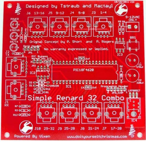
J1 is the data input to the Simple Renard 32 Combo
J2 is the data output from the Simple Renard 32 Combo
Outputs
The outputs of the Simple Renard 32 Combo is connected via straight thru Cat5 cables to SSRs.
J3 is Output channels 1-4
J4 is Output channels 5-8
J5 is Output channels 9-12
J6 is Output channels 13-16
J7 is Output channels 17-20
J8 is Output channels 21-24
J9 is Output channels 25-28
J10 is Output channels 29-32
RJ45 output jacks are wired as follows:
Pin 1 - +5vdc
Pin 2 - First Channel Output
Pin 3 - not connected
Pin 4 - Second Channel Output
Pin 5 - not connected
Pin 6 - Third Channel Output
Pin 7 - Ground
Pin 8 - Fourth Channel Output
Power Connections
Warning...The Simple Renard 32 Combo does not have an on-board fuse. You must use an external/inline fuse holder with a 1A fuse for the power input for safety.
The board is powered by connecting a 9-12vac power supply to the power input terminal connector on the upper right corner of the board. The power supply must be AC to generate the zero crossing signal for dimming ac circuits.
The on board voltage regulator circuit generates the +5vdc to power the on board circuits and provide switching signals to the attached SSRs.
Firmware
The Simple Renard 32 Combo makes use of a different PIC then the usual PIC found in most Renard devices. The Simple Renard 32Combo does not use the default Renard firm. You must make use of the special firmware listed below to program your Simple Renard 32 Combo. The Simple Renard 32 Combo firmware runs Renard protocol and is setup with start addressing to run with dirknerkle's RenW wireless boards. A DMX version is currently being tested and should be available sometime in May 2012.
The Simple Renard 32 Combo has one version of the software available.
- There is one version of the software that makes use of the full 32 channel.
Unlike typical Renard firmware, you must make changes to the .inc file, not the .asm file to adjust the operating parameters.
- You must modify the firmware in the .inc file to match the correct baud rate of your data network. The Simple Renard 32 Combo runs at 57.6k or 115k baud rate. The default baud rate is 57.6K.
- You must modify the firmware in the .inc file if you want to use a different start address for the device. The default address is 0 and you can find more info here Start Address Guide on start addressing.
- You must modify the firmware in the .inc file if you want to use ULN2803AN
- You have to uncomment this line
- #DEFINE DC_LED_LIGHTS ;;mostly used for ULN2803AN Darlington LED Drivers, DC power
- You have to comment out this line
- ;;#DEFINE TRIAC_OR_SSR_LIGHTS ;;used for Triac/SSR driven Incandescent or LED lights, AC power
- You have to uncomment this line
Note: If you want to use DCSSR's you should remove IC 3 (H11AA1) so ZC will not be used and this will allow PWM to function.
Downloads
Simple Renard 32 Combo Firmware (32 channels) SR 32 Combo
Simple Renard 32 Combo Beta DMX Firmware (32 channels)SR 32 Combo DMX
Schematic
File:SR 32 Combo v.1b Header Info 11222011.pdf
PCB
PCBs are available from N7XG (Dean) or kits are available at diyledexpress
Design Options
The Simple Renard 32 Combo is designed to drive either all DCSSRs or all ACSSRs, not a mix of SSRs. The unit is configured for DCSSRs by:
- Removing the ZC Chip
- Modify the firmware as noted above.
Other Information
TBD
Simple Renard 32 Combo Discussion Threads
Interest thread
Thread 1
Thread 2
FAQ
TBD
