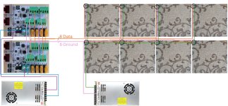
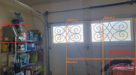
F48 & Differential Boards & Wiring

munu

Member
I have 8 20x20 matrixes. I plan to use them with two Falcon differential boards, each having 4 outputs so a total of 8 outputs. Preferably, I keep the control boards and PSU in the garage but I am open to other solutions. The cables have to go out the garage door so I would like to reduce the number of cables as much as possible. Hence, I think for the data I could use my 9 conductor, solid 18AWG wire for the sprinkler system. So in the garage I somehow combine all data lines into this one calbe. Then I have a 12V power supply with some 12AWG cable and fan out the power to the 8 matrixes. Power to the differential board will come from the 12V PSU so they have the same ground as the data. Does this work? Any other suggestion? I am not quite sure yet how to fan out the 12V power out of that 12AWG cable I plan to run from the PSU.
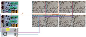
Wiring1.jpg
 
The data cables between the differential receivers and the pixel panels need parallel ground line(s), which should run from the panel input to the receiver data outputs. Whether just adding those wires without making any other wiring changes is something to think about. The Differential Receiver Power Consumption (Volt & Amperes), the length and gauge of the power/ground lines between the P/S and differential receivers as well as between the P/S and the first pixel panel would need to be known in order to know if there would still be problems or not.

P/S to Diff_Recv distance: nnn feet
P/S to Diff_Recv wire gauge: nnn AWG

P/S to Pixel Panel distance: nnn feet
P/S to Pixel Panel wire gauge: nnn AWG

Diff_Recv Power Input: 12V/nnn Amp
 
think about twisted pairs. each data wire must have a v- wire that travels WITH it. that means a cat5 cable can handle 4 pixel ports.
 
Sorry about my ignorance. So each 20x20 matrix has 3 inputs. V-, V+, D. I should have an external PSU providing power to all 8 matrixes. So run a thick cable (12AWG or more) and fan it out to the xConnectors of the 8 matrixes. So this "thick" cable just provides power to the two conductors of they 8 xConnector cables for each of the 8 matrixes. That's for power.

Then I should have 8 data cables from the differential receivers to the 8 matrixes/xConnectors. But they need some reference, i.e. the V- of the PSU that gives power to the matrixes. So I need to connect the negative line on the 8 differential receivers to the V- on the PSU. But it doesn't carry a lot of current so I probably can get away with some 18AWG cable for all V- on the differential receivers to the PSU?
 
you can use any psu to power the diff receiver and then you run the data and v- from the receiver to the first pixel, NOT to the psu. yes the psu v- and the diff receiver v- get tied together AT the first pixel.
 
Martin's suggestion is a huge step in the right direction, and is completely sufficient when there is a single data signal (v- and sig) connecting the controller (diff receiver here) and the pixel string and the differential receiver has a separate PSU. However, for the case where there are multiple pixel strings (or matrices) in parallel it's not a completely robust solution, depending on the lengths of the power cables from the PSU to the matrices. The problem is that the ground pins of the matrices may be at different voltages relative to the PSU ground, depending on the lengths and wire gauges of the power cables and on the instantaneous power draw of each matrix. Accordingly, the voltage on the ground at the differential receiver will be somewhat above the PSU ground voltage, which could (not necessarily would) put the signal voltage at some of the matrices below ground at the matrix input. Whether this happens or not and is an actual problem depends on the voltage drops across the various power cables, so I would recommend that the length of the power fanout cables be kept short.

My preference would be to provide complete galvanic isolation on the V- and Data signals that Martin mentioned as running from the differential receiver to the pixel inputs. This would mean that there is no DC connection between the V- of the controller and the V- at the pixel pin (except through the power input to the differential receiver, if it shares a common PSU with the matrices). This is similar to how 10/100/1000Mbit ethernet devices are designed using transformers on the controller inputs and outputs to provide multi-kV isolation. However, I don't know that such isolation devices are readily available for the hobby. I have designed and built such widgets myself, but my advice is to use thick, short power cables as well as following Martin's suggestions.
 
Let me give this another try with a new image. So what you are proposing is powering the differential receivers from one PSU. In the image below that's the PSU in the lower left. All it connects to is the GND and V on the differential receivers.

Next I use the data and V- line for each of the outputs (4 per board for a total of 8) and I route those to each of the matrices. The black circles are my 3 conductor connectors for each of the matrices.

Then I have a second PSU to provide power to the matrices. The V- on the PSU connects to the V- from the 8 outputs. In the image, I show these two conductors being connected at the beginning of the 8 matrices but in reality, I would run them directly to the 8 connectors of the matrices.

Finally, there is the V+ from that second PSU. That also goes to each of the matrices and connects to the 3rd pin/V+ of the 8 matrices.

Maybe I misunderstood something but with this setup, I still have the differential receivers and the matrices on the same V- so there is no isolation.

Also note that the maximum distance from the differential receivers to the matrix the furthest away will be about 25 feet/8m. I will be using 16AWG cables (the pigtails from Wu are 18 AWG). I purchased some 16AWG 3 conductor cable and should get it soon but I guess I should have purchased 16AWG 2 conductor cables...
Matrix2.jpg
 
what you have will work. Phil is a purest. proper design would be to isolate the wires from the receiver. most of us take a shortcut and skip the isolation and risk damage to the hw from voltage spikes.
 
I think that Martin is right, the setup that you depict is fine as far as power is concerned, since you'd have to try pretty hard to break it (especially if the maximum pixel current draw is 1A/50 pixels).

The 8M length of a data cable is getting to be a bit long, although some people on the internet seem to think that should be OK. I think that the V- and data wires between the differential receivers and the pixels should bes twisted pairs for noise immunity purposes, although Martin might say that I'm being purist here as well (as though that's a bad thing).
 
Being a purist is a GOOD thing. My engineers keep giving me a hard time for driving to such goals. I regularly get slapped with the "This is what it will cost to do it your way" and then I have to give in to a compromise.

I am a bit confused about why there is such a long distance from the receiver to the first pixel. IMO, the point of the remote receivers is to get them as close to the prop as possible. My remote receivers are mounted in my props and rarely have more than 1m to the first pixel. I DO have some pixel feeds in the 8m range but I have a data booster in those lines (I ran out of receivers).

YES ABSOLUTLY use twisted pairs for long data runs. A CAT5 cable makes a great long haul data cable. It twists the d and v- wires and encases them in a shield that you can tie to ground.
 
Showing my ignorance, what does the differential board do? Is it anything more than convert differential signals to single-ended signals (along with lots of fuses and connectors for providing power for the pixel strings/strips/matrices)?
 
they are called smart receivers. basically four diff pairs over cat5. has an asic to allow diasy chaining and generate test patterns.
 
Is the software capable of dealing with rotated sub-matrices? If so, it might be worthwhile to rotate the panels so that the inputs to the four left-panels are all adjacent in the middle of those four, and likewise for the right-panels.

And furthermore, if it was my display, I'd design a small replacement board for the differential receivers to place in the locations where the power connectors 'fan' out. These boards would each use an am26C32 chip (and termination resistors and connectors), giving up the daisy-chaining and test-mode features). This scheme would keep the critical data and power cables to the pixels as short as possible. But that's just me.
 
It's a bit messy and right now mounted inside the garage. But you can (partially) see 4 of the 8 matrixes. The F48 is on a shelf inside the garage. That's where I plan to keep it. There is another box with 2 differential receivers in the lower right. I was planning to put that right next to the F48 box. I know, then why use differential boards? But it's just for this prop where it happens to be very close. For other props (future) the differential receivers will be outside.

With 8m I probably stretched it a bit. The garage door is 16' wide and the connector furthest away, is probably 13 feet from the left side of the garage. Another 8 feet to go into the garage and onto the shelf. So about 21' = 7m. I am not sure where I would put the differential receiver and PSU if I placed it right next/into the matrices. I would have to hang it somehow from the garage.

But I am considering to have just a 12AWG cable from a PSU inside the garage going to all 8 matrices. Then have two Ethernet cables to provide the data to the 8 matrices (16 conductors, 8x D and 8x V-). So now I am down to just 3 cables instead of 8 cables and based on the input here, it's a better way to do it anyways. I just need to change my box with the differential boards. And I hope using "thin" (21AWG at best but probably 24AWG or even 28AWG) twisted Ethernet cables work better than the 16AWG non-twisted cables I was going to use (should be delivered this weekend). https://www.amazon.com/dp/B0C6HZF8X3


GarageSetup1.jpg
 
What will be the distance between the garage door and the matrices (when they are mounted on the exterior of the garage door?
 
I took out a tape measure. The longest run will be around 18'. Each matrix pulls about 3.5A at white and full brightness.

I checked your advice about the direction of the matrixes. The mounting actually allows me to put them upside down. So I could have the connector for the upper 4 in the middle rather than the top (if I flip them). And the lower ones already have the connector at the top (so the middle). Hence, I could run power and data straight through the middle. I am pretty sure the software allows me to take care of the matrices on the top being "upside down". Something I need to test this weekend.
 
Back
Top