fm transmitter

If it calls for a 10uf/35v, the 10uf/50v would be okay but I'd be a little hesitant to go for the 10uf/16v. It depends on how much voltage *might* go through that cap. That's what the safety margin is for because you don't want one to blow up.

thankls a bunch for that I was thinking the higher rated voltage one.

Also I dont supose any of you would know what parts I would have to change to what values to run a 2SC1972 as the final instead of the 2SC1971 the only diferance between the 2 is the 2SC1971 has i belive 6W output and the 2SC1972 has 14W but a lower gain than the 2SC1971, Thought I would ask on here as you all seem to know what you are doing, I did ask on the pira forum but just got a stupid answer somthing about the gain of the transister determins its output so the 2SC1972 would produce less W output, Dont get this as it is rated as 14W wher as the 2SC1971 is rated at 6W

I don't know the product you are talking about, but the response you got may be correct. The gain Output Stage of a an RF Amp is usually a low gain hi power device. the intermediate stages would also need changes if you intend to run at a higher power. Other areas you would need to address the impedance matching between stages.
 
I don't know the product you are talking about, but the response you got may be correct. The gain Output Stage of a an RF Amp is usually a low gain hi power device. the intermediate stages would also need changes if you intend to run at a higher power. Other areas you would need to address the impedance matching between stages.

Ok thanks although you lost me at intermediate stages.
I dont have a clue what each bit on a transmitter actualy does I just know how to follow build instructions and how to make my own PCB's oh and how to solder.
Thanks for the reply though
 
how imperative is it that 0.8MM wire is used to form the coils as I dont seem able to find any anywhere in the uk Cheapley and dont want to fork out £12 on a roll online just to make 4 coils, I do have a roll of 0.71 MM tinned copper wire
 
thankls a bunch for that I was thinking the higher rated voltage one.

Also I dont supose any of you would know what parts I would have to change to what values to run a 2SC1972 as the final instead of the 2SC1971 the only diferance between the 2 is the 2SC1971 has i belive 6W output and the 2SC1972 has 14W but a lower gain than the 2SC1971, Thought I would ask on here as you all seem to know what you are doing, I did ask on the pira forum but just got a stupid answer somthing about the gain of the transister determins its output so the 2SC1972 would produce less W output, Dont get this as it is rated as 14W wher as the 2SC1971 is rated at 6W

It wasn't a stupid answer, so hopefully you were a little more polite to someone that was trying to help you. :-x :-x

The gain of the transistor DOES determine the output. For example, say that transistor "A" has a gain of 7 and transistor "B" has a gain of 5. We'll also say that "A" is rated for 6 W max, while "B" is rated for 14 W.

So, if the drive input to the transistor is 1/2 W, the output of "A" would be 3.5 W, and the output from "B" would only be 2.5 W, even though it has a higher power rating.

The rating is for the maximum power that the transistor can handle without burning up. It doesn't magically create power.

In order to get more output, you would have to get more drive to the output stage. Also, the power supply needs to be adequate to support higher power output.


how imperative is it that 0.8MM wire is used to form the coils as I dont seem able to find any anywhere in the uk Cheapley and dont want to fork out £12 on a roll online just to make 4 coils, I do have a roll of 0.71 MM tinned copper wire

That would depend on how critical the coil design is in the unit. Changing the wire size will have an effect on the inductance value, depending on the turn count and spacing, as well as effecting the capacitance between turns. without knowing the details, any answer to that question would be guesswork. Since this is a DIY board, the most likely answer you'd get here is "Try it and see!!" Good luck... :rolleyes: :rolleyes:


:)
 
Last edited:
Just a question....

Who has built one of these besides Tim?

I know several of us have one in the works. I have my DS board etched and drilled and hope to get to building on it next week.

Any input on other's experiences would be helpful.

thanks,
Chris
 
I never did get mine finished, but it's REALLY close. All it needs is the jacks and then to figure out how to connect all the boards together and power up and test/adjust. Hopefully I can get it working for 2010.

I was hoping for help from Tim on this thread.

For 2009, I had to buy a FM-02, which worked OK, by the way - the range was only about 400' and then the signal dropped off fast.
 
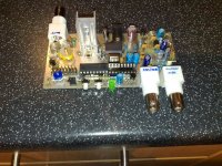
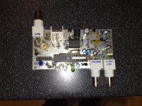
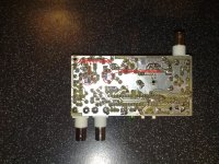
Well mine is all done now I am just waiting on another TSA5511 as the first one I purchased I screwedup trying to get it on the dil socket as they come wider than the dil. Its ok to build unfortunatly I lost a few of my tracks on mine soon as I tooched the soldering iron on they just peeled right off, and thats with a board purchased direct from pira, luckly both tracks wher in places where I could leave the legs of a component slightly longer and bend them over to sort of reform the tack.

posted some pictures for you.
 

Attachments

  • 10042010029.jpg
    10042010029.jpg
    237.1 KB · Views: 79
  • 10042010030.jpg
    10042010030.jpg
    178.7 KB · Views: 65
  • 10042010033.jpg
    10042010033.jpg
    229.4 KB · Views: 60
Last edited:
Nay27uk,

I am wondering what country you are in. The basic design here is a 5W transmitter. The one most of use are building omits the final transistor to keep the total gain down to below 1W. In the US, even a 1W xmitter can get you in real trouble! A 5W will most certainly get you in serious trouble.

Cheers,
Chris

I am in the UK m8 thanks for the concern though
 
Hello i know that is an old thread BUT i have just done the tx pira transmitter and i need little help please what software do i need to open the .asm file and change the start up name and recompile to .hex file thank you and merry chritmas in advance for this year 2016 :)
 
there is no pdf file size but i have resised it on irfanview 134 mm and 67.8 mm aspect ratio .can anyone change to me the hex file for transmitter pira start up i want to put my station name REVE FM

merry christmas and happy new year
 
Good info DMC...
A Dipole is a very simple yet effective antenna. Technically called a Half Wave antenna where the radiating element is 1/4 wave and the ground plane is 1/4 wave(typical 3db gain)

Sorry to be picky, but the first part of the above is correct, but the dipole only has "gain" over an isotropic aerial - which only exists in theory! The dipole exhibits 0dB gain, as it's used as the reference point for all real antennas with actual gain! Therefore your 125mW into a dipole will be (neglecting slight losses) 125mW radiated.

Other aerials that don't show gain over a dipole include the quarter-wave ground plane type.

In the Real World™ you'll find that you'll incur some losses. Your antenna feeder will be (slightly) resistive and will show capacitance between the centre conductor and the braid - both will incur losses (which increase as the feeder length increases, of course). Also, your dipole will present a symmetrical load of about 72Ω (if it's the right length), so you're going to have to make your asymmetrical feeder into a balanced feed to properly match your dipole. This can be achieved most easily by means of a "Pawsey Stub" or (trickier) a quarter-wave phasing loop. Other feed options include the "Gamma Match" which works very well but makes the antenna more complicated.

My favourite approach for very low power FM installations (I used to install lots of Drive-In cinema systems) was to use TV coax (the 75Ω characteristic, brown-sleeved stuff available in any hardware store), and a Balun (actually an "Un-bal" because we're going the other way!), made from a ferrite bead with (typically) six turns bifilar for the two windings. This works very efficiently with a dipole up to about a Watt.

One little transmitter I worked on was a small phase-locked loop design, with a pair of identical ¼Watt output stages driven in phase opposition, and connected directly to the antenna elements, so eliminating losses and matching issues. The little transmitter was housed in a small waterproof diecast box, and it was fed DC power and modulation signals up a multi-core flex from the ground below. The box was equipped with a clamp to allow it to be attached easily to a mast / boom arm arrangement. The antenna elements had telescopic ends, and the manufacturers provided a calibration chart of antenna length against operating frequency! This little device could be set to any frequency from 76 to 108 MHz in 100kHz steps, so could cover both the Japanese and European / American ranges of frequency.
 
https://web.facebook.com/k19radio/p...QZz9dpzr7LDXyzA9mMWhxdX3BEnasjdacp5dKYJ4EaYtl

Pira PLL 5W transmitter review 2023
A review of the famous Pira PLL 5W transmitter in 2023. Since there is no detailed analysis from that time, we conclude that it was certainly never possible to have 7W of pure signal. We measured pure 5W at 14V, and that is the best that can be achieved for a pure signal that "does not need" after LPF. However, we had to make some changes to the basic circuit to achieve this.
Of course it is possible to reach 7W 8W but with enormes of spurs and harmonics.
 
Back
Top