Good info DMC...
A Dipole is a very simple yet effective antenna. Technically called a Half Wave antenna where the radiating element is 1/4 wave and the ground plane is 1/4 wave(typical 3db gain)
Sorry to be picky, but the first part of the above is correct, but the dipole only has "gain" over an
isotropic aerial - which only exists in theory! The dipole exhibits 0dB gain, as it's used as the reference point for all
real antennas with actual gain! Therefore your 125mW into a dipole will be (neglecting slight losses) 125mW radiated.
Other aerials that don't show gain over a dipole include the quarter-wave ground plane type.
In the Real World™ you'll find that you'll incur some losses. Your antenna feeder will be (slightly) resistive and will show capacitance between the centre conductor and the braid - both will incur losses (which increase as the feeder length increases, of course). Also, your dipole will present a symmetrical load of about 72Ω (if it's the right length), so you're going to have to make your asymmetrical feeder into a balanced feed to properly match your dipole. This can be achieved most easily by means of a "Pawsey Stub" or (trickier) a quarter-wave phasing loop. Other feed options include the "Gamma Match" which works very well but makes the antenna more complicated.
My favourite approach for very low power FM installations (I used to install lots of Drive-In cinema systems) was to use TV coax (the 75Ω characteristic, brown-sleeved stuff available in any hardware store), and a Balun (actually an "Un-bal" because we're going the other way!), made from a ferrite bead with (typically) six turns bifilar for the two windings. This works very efficiently with a dipole up to about a Watt.
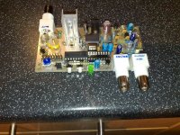
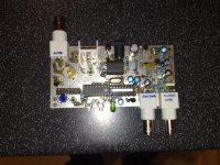
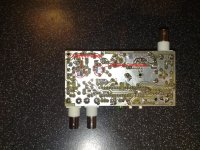
One little transmitter I worked on was a small phase-locked loop design, with a pair of identical ¼Watt output stages driven in phase opposition, and connected directly to the antenna elements, so eliminating losses and matching issues. The little transmitter was housed in a small waterproof diecast box, and it was fed DC power and modulation signals up a multi-core flex from the ground below. The box was equipped with a clamp to allow it to be attached easily to a mast / boom arm arrangement. The antenna elements had telescopic ends, and the manufacturers provided a calibration chart of antenna length against operating frequency! This little device could be set to any frequency from 76 to 108 MHz in 100kHz steps, so could cover both the Japanese and European / American ranges of frequency.