FPP PB16 Pixel Controller

I've never built one of these diff receivers, so I don't know the spacing. There are a couple of free ones here for an older style F8 distro and for a RPi:

https://inspirelightshows.com/product-tag/free/

If these wouldn't work, and you know the dimensions of the hole pattern (in mm), and have an STL file (or using one of the above), I'd be happy to hack it up in F360 and make an STL for you.

EDIT: or Glycerine can do it - lol :)
 
Last edited:
Good afternoon everyone. I have looked through the thread, but have not found what I was looking for. I have built a few differential receivers and was wondering if anyone was aware of a STL file for a meanwell/ differential receiver mount. I found them for the falcon, but it doesn't appear the mounting holes are in the same spot
Thanks

I know it's not an answer to your question, but if you've never used Tinkercad, take a look at it. I was in need of some parts to complete some props this year, and was surprised at how easy it was to model what I needed in Tinkercad.

If you don't find an stl soon and don't want to try it yourself though, I could mock something up for you.

EDIT: Or puppycrack can do it :)
 
Good afternoon everyone. I have looked through the thread, but have not found what I was looking for. I have built a few differential receivers and was wondering if anyone was aware of a STL file for a meanwell/ differential receiver mount. I found them for the falcon, but it doesn't appear the mounting holes are in the same spot
Thanks

Please do not hijack this thread. If you have questions about 3d printing, please go to that forum and ask there. It is hard enough going through this long thread and find the information you need to make this build. Thanks.
 
Please do not hijack this thread. If you have questions about 3d printing, please go to that forum and ask there. It is hard enough going through this long thread and find the information you need to make this build. Thanks.

He's referring to one of Scott's diff receivers, so it's valid to ask here.
 
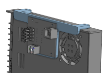
This is completely untested, but I made some Meanwell mounts for you. Let me know if they work.

2023-01-07_14h17_28.png

https://www.printables.com/model/362115-pb16-receiver-out-meanwell-mounts


Thanks,
Scott


Good afternoon everyone. I have looked through the thread, but have not found what I was looking for. I have built a few differential receivers and was wondering if anyone was aware of a STL file for a meanwell/ differential receiver mount. I found them for the falcon, but it doesn't appear the mounting holes are in the same spot
Thanks
 
Thank you, Scott! I'll be printing this today and will let you know how it turns out! I downloaded Tinkercad, but hadn't had enough time to work one up with younger kids at home. I'll come back later with photos!
 
I printed out the mounting bracket today and the receiver board mounted perfect. I used some thread rolling screws I had sitting at work to mount the receiver to the bracket. My only meanwell supplies are sitting in my main enclosure so I could not mount the board to that to verify fitment to the meanwell. Thanks again Scott! Your awsome!20230110_191729.jpg
 
This question goes out to Scott or anyone using a BBB16 with the differential expansion board.
The differential port on the BBB16 is for Strings 17-20, when using it off the BBB16 board is the jack on the expansion board disabled for 17-20?
Or.....when the expansion board is plugged in, is the port on board the BBB16 disabled?
Just building these boards now and wondered about the overlap of 17-20.
Thanks.

Nix this.....
I just finished board and loaded FPP.
Once configured it shows 17-20 as its own differential receiver and then a block 21-36 for the expansion.
So, you get the 4 strings on the mainboard plus the 16 strings with expansion.
Awesome!
 
Nix this.....
I just finished board and loaded FPP.
Once configured it shows 17-20 as its own differential receiver and then a block 21-36 for the expansion.
So, you get the 4 strings on the mainboard plus the 16 strings with expansion.
Awesome!

Good to know. Thanks for the update. I don't have that version of the board, but was still wondering what the answer was!
 
Is there an updated BOM for board v1.0g? I am finally ready to build a couple of these, but never bought the components.
 
With the FPP 6 license stuff I cannot generate EEPROMs anymore, I upload a JSON file of the pinout that you can send to Chris to generate the EPPROM.

Uhh... What does the FPP6 license stuff have to do with generating an eeprom at all? You should still be able to generate an unsigned eeprom with your cape-info, default configs, string config, etc...
 
Sorry maybe I didn't understand the license process correctly, I thought Chris had to generate a EEPROM with the "99" signature included in it.

He needs to start with an actual eeprom.bin file for the board. That would then be signed as part of either process. For the DYI stuff, he would take the bin and sign it and send it back (I think). If the user preferred to purchase the license (generally faster, can be done in minutes), the eeprom would need to be already flashed on the board and then everything can be done from the cape-info pages in FPP and in the store. Either way, the eeprom.bin for the board is the important starting point.
 
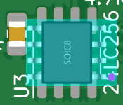
I'm trying to use JLCPCB to create the BBB_16_Flex version of this board. I'm running into an issue though when I get to the product placement screen. All the components are in the right places, but their orientations are off. Someone made a similar comment a few pages back on this thread and it seems as though it is caused by changes to the JLCPCB website awhile ago. For the most part it's simple enough to orient them correctly as the resistors shouldn't matter and most of the others are labeled with a + sign. However, the chips are a little harder to figure out as I don't see any markers for pin 1 goes. For one of them, U2, I was able to figure it out by looking at the picture. The other one though, U3, isn't in the picture as it is covered up by the OLED screen. Does anyone know which way to rotate this part? Also, does it matter for the capacitors? I thought these are usually polarized, but I see nothing on the board nor the piece to rotate on the screen as to which side is supposed to be positive (see C3 as an example).

orientation.png
 
What exactly are you trying to do?

I'm guessing that you are attempting to use the files that Scott placed on github to have jlcpcb fabricate the boards and and then have jlcpcb assemble those boards. Is this so, or are you trying to do something else? In any case, pin 4 of the 24LC256 is ground, so just examine the gerber files to determine which of the two corner pins (NW, SE) goes to ground, and that will be pin 4.
 
Back
Top