How do I remove 8 function controller from light string?

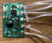
Another controller. This one for a super long Rope Light. The Heatsinks on the Triacs broke the board so I want to be able to control this with an SSROZ. Pictures attached. Any suggestions. The Rope light has a label on it for approx 5 volts but no big tranny. I take it is on the board. I wish they would standardize these things....
Josh
 
Josh,

is there markings on the rope light stating that it is 240v rope light?

Be very careful with anything to do with 240v and if you are unsure, don't do it.

If you are sure that it is 240v rope light, look at the circuit board where the rope light solders to it and after careful study you will find that two of the wire will connect to the triacs, these are your switched or active wires, one for each colour, and the third wire will be the return or neutral wire. Connect the neutral wire of the rope light to the neutral wire of the 240v input. This does not get connected to the SSR.
Connect each of the rope light active wires to the output of your SSRs and connect the 240v active wire to the inputs of your SSR.
You should now be able to control your rope light.
Ensure all your connections secure and that there is no bare wire and encase it all in plastic box.

I would highly recommend that you power it through a safety switch to be sure.
I have modified some Mort Bay rope light like this and it works well.

Jon
 
Thanks for the reply. The rope light is 240 volt at the plug and unless there is something on the board that drops the voltage it must be 240 volt. I guess that was my question in the start. So long as none of the elements on the control board drop the voltage than this seems rather simple. I guess the smart thing to do is use the same heatsinks on my SSR triacs.
Thanks for the tips
Josh
 
unless there is something on the board that drops the voltage it must be 240 volt.
Josh

Yep... you are right.

But I'm still a bit worried about that little transformer-like thing on the board. What's it for??? Might not drop the voltage... or might........

(Might, say, halve it??? Depends on the ropelight)

However, The 5V tag you mentioned is not making much sense when you look at the rating on the capacitors and the size of the connecting wires. Super long ropelight at 5v will require lots of current!

So be careful. Firstly to protect yourself. Secondly to protect the lights!

It might be a terrible waste to guess and get it wrong...

Really need to take care with this 240V stuff. As already mentioned, please get someone who knows what they're doing to look at it if you aren't sure. This is a very different proposition to the 24V circuits we were playing with earlier in this thread.

Safety switches are always a good idea.... But if thats a step down transformer the safety switch isn't going to provide total protection at present (and you're probably going to wreck the lights if you connect them to 240V). Seems to me the smart thing is to figure this out before you connect the lights directly to ssroz @ 240V!

Bottom line - I'm not sure we've got to the certain answer on this yet... apart from the need to be careful.....

(Have I said "be careful" enough yet? :) Its important!)

Tim
 
Thanks for your help Tim. I bit the bullet and just wired the 240V plug to the rope light string Crossed my fingers and flicked the switch. It worked. All that is left to do is put that SSR in the way.
Thanks for all your help guys.
I am yet to play with the LED's though. I will let you know how I get on.
Its all getting a bit close now.
Josh
 
Crossing your fingers and flicking the switch works sometimes. But not the recommended approach!

Glad it worked and you're all in one piece. :)

Tim
 
As part of this thread has been talking about using a rectifier to feed power to an ssr to drive strings of leds from the outputs i was wondering if anyone knows if you need to change the value of the gate resistor on the ssr. If your using 230v the gate resistor value would be 330 ohms but if you rectify it through a full wave rectifier the voltage is effectively 230 * 1.414 = 325 Volts. So do you change the gate resistor to be around 480 ohms or will it still be okay at 330 ohms? Any help would be greatly appreciated.
 
Hi,

I almost got it going ��. However one of the four strings isn't working ��. Can you help me please?

Colin in Scotland
 
Last edited:
Hi would you be kind enough to advise on which wires need combining on the following controller so that they stay ‘on’

74B9A931-F16C-4E83-A00B-279F1ED207CF.jpeg

Many thanks H
 
Need a bit more data.

How many "strings" of lights are there?
Do the individual lights support multiple colors?
Have you measured the voltage on the strings when they are full on?
What does the other side of the PCB look like?

The picture leads you to believe there are either 2 or 3 strings of lights. Two of them have the controlling devices on the front of the board. There is a third pad with no controlling device. Is that the common line?
 
Hi,.. wow.. omg... erm.. these are icicle lights.. not multicoloured...
I can’t measure voltage as I’m a complete novice..
The rear of the pcb is blank.. does this help..
 

Attachments

  • CamScanner 07-05-2023 13.00.pdf
    421.6 KB · Views: 8
  • CamScanner 07-05-2023 12.59.pdf
    274 KB · Views: 6
HI there,

I have been following this thread trying to remove or bypass the 8 function multi-controller for the lights I have here...https://www.amazon.com/gp/product/B08C2R6VFK/ref=ppx_yo_dt_b_search_asin_title?ie=UTF8&psc=1

I would like them to just turn on and off only. They are only one color (white) and there were only 2 wires coming out of the controller when I took it apart. Any advice would be greatly appreciated.
This product link points at a non adjustable product. It has a PSU but no "functions".
 
Sorry, are you referring to the Amazon link to the lights I have purchased? The lights I have are connected to a small controller with a button I can press to cycle through different animations (blinking chasing etc) How can I remove or bypass that so they just turn on and off when power is applied?
 
Thank you so much for getting back to me. Sorry, are you referring to the Amazon link to the lights I have purchased? The lights I have are connected to a small controller with a button I can press to cycle through different animations (blinking chasing etc) How can I remove or bypass that so they just turn on and off when power is applied?
 
Do they remember last turned on value? Then you can just connect them to a renard. But since you already cut off the controller, likely you will need a 30v power supply and connect that directly to whatever wires you have. I DO NOT HAVE these lights and so you could blow them up. But the power label said they are 30V DC lights. Often, there is protocol running under the voltage output that is sending "dots and dashes" and a slight bit of logic on each light that interprets the dots and dashes.

How are the LEDs wired. Two wires in and two wires out with 2 wires for power injection? Or are they wired every other?
 
Back
Top