ErnieHorning
Supporting Member
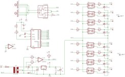
Here are the pin definitions.I’ll look around, I have the pin definitions for the D-light board somewhere...
You can get up to 3 free sample on Microchip.com.Ok, what do I need to do to get new micro's.
There’s a free development IDE tool called MPLAB that you can use to write assembly as is. You can also attach third party tools if you want to write in a different language.What Software and hardware.
You’ll also need a programmer. I use MPLAB IDC2, though there are cheaper programmers. You compile and program through MPLAB.
 . Anyway, I am more than willing to do any legwork. Most of this is over my head but I feel I can help map out the board as far as I can without an oscilloscope. Are we still thinking that loading a modified Renard firmware will allow us to use vixen? Or would it be easier to write an output plug-in for vixen?