Setting up HLS Channels
Revisions of this document are in process.
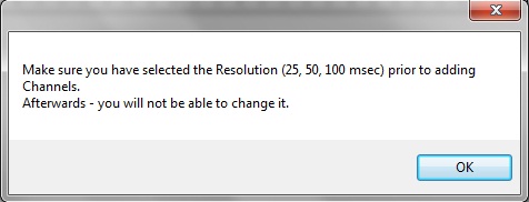
Next we will set up output channels. Click on the Manage Channels tab at the top of the page and then click on Manage Raw Channels. At this point you will see a message reminding you to choose your time period resolution before you continue (see Figure 1-5). Next, click on the OK button.
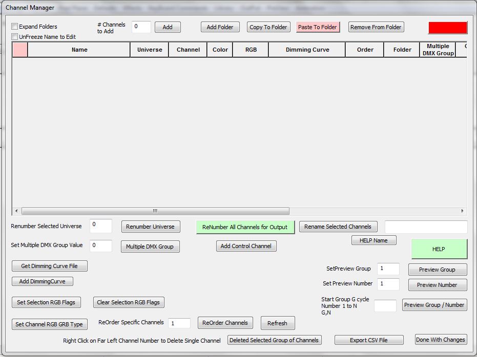
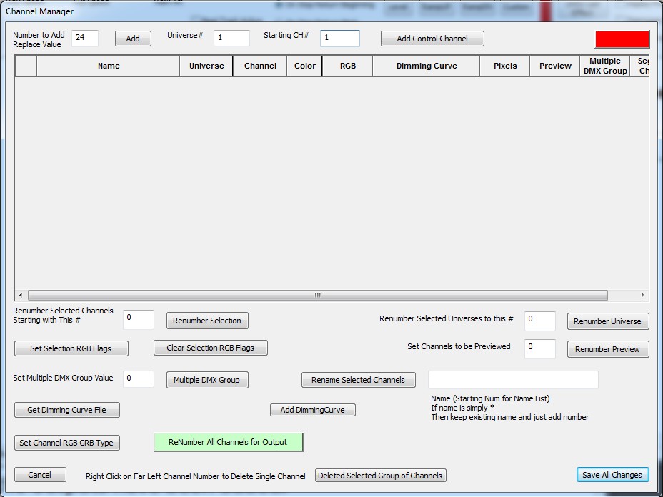
The Channel Manager screen will now as appear (see Figure 1-6). This is where we will add and configure channel outputs. For this example we will use a Renard 16 and a Renard 8 module. This would be 24 outputs total. We do not have to tell the software we have two controllers in this example as they are both Renards and they will both be attached to the same com port. There are three entries we will need to change at the top of this screen. First right next to the Number to Add/Replace Value entry enter 24 for your 24 (16 +8) outputs.
Next, change the Universe # entry. It cannot be zero for real outputs. In this example we will only have one type of controller and one port so we will only use one universe. 1 was entered for this example. Next, the starting channel entry was changed to 1 to correspond to the first channel (output) in a Renard being 1.
Once these three changes have been made, click on the Add button to actually add the new channels. See figure 1.7
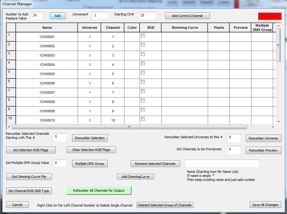
Figure 1-8 shows the screen after the outputs have been added.
The following tutorial was based on Version 11F
Examine output 1. Note the name of the output. It is 1CH1. The first one means it is in universe 1. The 1 at the end means it is output channel number 1. We will change the names to reflect their use. In this example we will have two trees: Tree_1 and Tree_2. Each tree will have 3 outputs. The first output will be red.
Click directly on the text for channel 1 (1CH1). Replace the name with Tree_1_Red (see Figure 1-9). Next the names for outputs 2-6 were entered.
The color was chosen for each output next. The color will be used in the simulation. To set the color for an output you must choose the desired color in the upper right of the screen (see Figure 1-9). In this example Red was chosen. Next you must Click on the Active Color Selection check box right next to the color box in the upper right corner. At this point you have chosen the desired color and checked the Active Color Selection check box.
Next right click in the desired channel row Color box and it will change to the chosen color (see Figure 1-9).
Figure 1.9
The same process was followed to assign the green and blue colors to outputs. Note that this screen can also be used to renumber universes and or renumber output channels.
We are now done with this screen, click on the Save All Changes button.
| HLS User Manual and Reference Guide | ||
|---|---|---|
| Previous Page | Current Chapter | Next Page |
| Chapter 2: Creating a Sequence | Chapter 3: Channel Management | Configuring Display Groups |


