The GRINCH Controller
Jump to navigation
Jump to search
Background
- There are a myriad computer based controller hardware available that will run under the Vixen software. While Robert Jordan was working on his LEDTRIKs, a LED panel based display, he noted that the same driver IC chip could replace two different types of chips used on the Olsen 595 COOP board.
- Robert’s aim was to come up with a circuit design for a controller that was smaller, cheaper, and easier to construct than the Olsen 595. He had to give it a name and decided on the ‘GRINCH’ after his favorite Christmas movie. The details of his prototype are detailed on the Computer Christmas website here.
- The GRINCH does what you expect it to do – it makes lights flash under control of Vixen. It does not have Channel LEDs, it does not dim lights, and it does not use PICs. The GRINCH does work and it is cheap!
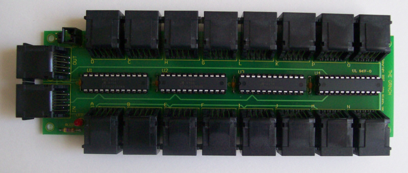
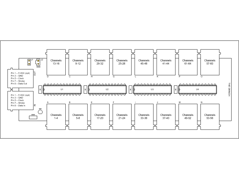
The Board
Simplified Theory
- This is a real simplified explanation of how the data flow to the GRINCH works.
- The VIXEN program controls all data communication between the PC and the GRINCH.
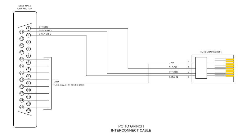
- VIXEN uses the DATA BIT0 pin (pin 2) of the parallel port to serially feed data to RJ45 IN connector pin 8 on the GRINCH.
- VIXEN uses the STROBE pin (pin 1) of the parallel port for the clock signal to RJ45 IN connector pin 5 on the GRINCH.
- VIXEN uses the AUTOFEED pin (pin 14) of the parallel port for the strobe signal to RJ45 IN connector pin 7 on the GRINCH.
- VIXEN pumps out the channel data in reverse order, channel 64 first and channel 1 last (assuming a single GRINCH setup). This is due to how the data is clocked thru the serial shift register section of the IC chips. As VIXEN sends out data for each channel, it will also send out a corresponding clock signal so that the data can be clocked into the IC chips. At this point the data is only being held in the IC chips and the outputs of the chips will not change. Once all the data has been sent to the GRINCH, then VIXEN will send out a strobe signal followed by another clock and that will latch the data in the IC chips to the output pins. This process is repeated whenever VIXEN needs to update any channel data.
- A key thing to remember is that when VIXEN shows a channel as ON, the corresponding output pin of the GRINCH will be sinking signal and not a sourcing signal. This means for every channel that should be ON you should have 0 VDC (GND) on the corresponding output pin. This sinking signal is what the SSR boards require to turn on the desired AC connection.
Circuit Diagram
- The schematic diagram for the GRINCH can be downloaded here.
- The circuit is based using four 16 bit constant current LED sink driver integrated circuits. Currently, these are the tested/proven and readily available IC chips for use on the Grinch board.
- MBI5026GN & MBI5027GN - available from King Electronics
- A6279A – available from Allegro Microsystems
- Differences between the IC chips:
- Recommended Operating Voltage Range (VDD):
- MBI chips = 4.5 – 5.5 VDC
- Allegro chips = 3.0 – 5.5 VDC
- Recommended Operating Voltage Range (VDD):
What this means to you: The Allegro chip is more tolerant of operating at a lower VDD. So if you are having problems detecting the signals coming from your PC’s parallel port you can lower your VDD and it might solve the problem.
- Incoming voltage level for a valid HIGH signal:
- MBI chips = 80% of VDD
- Allegro chips = 70% of VDD
- Incoming voltage level for a valid HIGH signal:
What this means to you: If you are supplying 5 VDC to the GRINCH as the VDD, then your PC must have at least a 4 VDC signal out of the parallel port to properly trigger the MBI chips and at least 3.5 VDC to trigger the Allegro chips.
Connection
- The GRINCH is connected to the controlling PC via a cable from the PC’s parallel port to the RJ45 IN connector on the GRINCH.
- Multiple GRINCH boards can be daisy chained together by connecting the RJ45 OUT connector of the first GRINCH board to the RJ45 IN connector of the next GRINCH board.
Powering the GRINCH
- The GRINCH requires an external power source to operate. The normal voltage requirement for a single GRINCH would be 5 VDC at about 1 Amp. There are two options for applying power to the GRINCH.
- Option 1: Apply the external power directly to J2, pin 1 – 5 VDC and pin 2 – GND
- Option 2: Bring external power in via the RJ45 IN connector on pin 1 (5 VDC) and pin 3 (GND). With this method you would also need to place a shunt (jumper) on J1.
- There are many options of what to use for the external power source. Some users prefer to use an unused hard drive power connection inside the computer that is being used to run VIXEN. Others prefer to use an old computer power supply that they modify to run as a stand-alone power supply. And there are others that have had success in using wall-warts but care should be used with wall-warts since not all of them provide a regulated/filtered output.
- When connecting multiple GRINCH boards together you must have a shunt (jumper) on J1 for both boards being connected to allow the operating voltage to be passed from board to board.
Computer Setup
- BIOS Settings
- The GRINCH appears to work best (for most users) if the parallel port is set to EPP in the computer BIOS. If you can't get it to work in EPP mode, try all other possible modes to see what works on your computer.
- VIXEN Settings
- The GRINCH uses the OLSEN 595 plug-in.
Layout
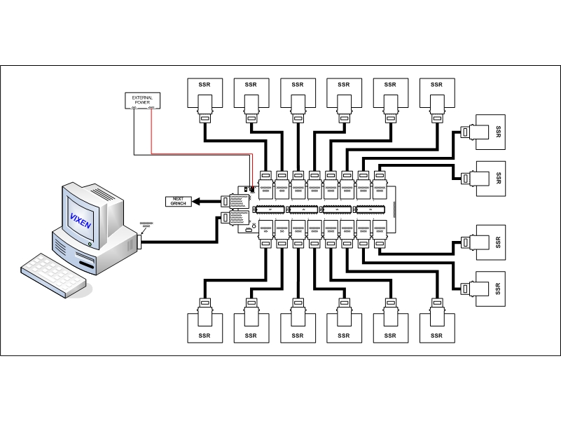
- This image illustrates a simplified depiction of how a typical display using the GRINCH would be configured.
- The GRINCH needs to be fairly close (less than 30ft) to the controlling computer due to the signal strength out of the parallel port.
- The SSRs can be placed anywhere needed in the display. They can be placed right next to the GRINCH or as far away as 800ft (farthest known test done).
Setup for Beginners and Troubleshooting
- If you are unsure that you have built your hardware correctly, you should follow the procedures contained in the Grinch Beginners Setup Guide. These procedures will guide you through the steps to help setup the hardware for the first time.
- If you encounter any problems with your Grinch, you can go to the Grinch Troubleshooting Guide. This page contains a methodical process to try to isolate problems/malfunctions and gives suggestions of what to do to fix them.
Upgrades
- Dimming
- The GRINCH can be made to do dimming by adding the REN-T and REN-C boards to the setup. More details on how these boards operate can be found on their wiki pages.
- DMX512 Communication with Dimming
- A DMX512 converter is available that will create the required signals and power for the GRINCH controller using a DMX512 signal and provide 64 channels of dimming. More info can be found HERE.


