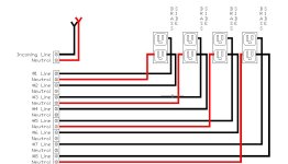
Does this look right my outlets

Pcguy17

New member
Edit post #47 should now be the correct way.


okay, I hooked it up just to find out if it's right don't worry I'm not going to plug anything in. I still waiting to get my SSR
but trying get this project closer. I built a encloser todsy to hold the SSR and these outlets. plan to use the socket that has all 3 leads in the box for a regular socket so I could plug my 5v power into it or a power supply or whatever I might need... I have power wire to each outlet to the next.. the lables are for the wires that will be coming from each of the 8 SSR I've cut the hot tab on all 4 outlets that's mounted so I can have 2 separate outlets on each one.. I relized at least I think i have to run a hot wire from.the one socket to the SSR board also then kinds like I did with the outlets piggy back from one ssr channel to the next one.. correct?
I have try to read and watch videos and there are a ton of videos showing people's hooked it up but Noone really explains at least for this guy how to connect it where I 100% understsnd..
electricity isn't something I like to play with if it was just 12v ild just try it and say heck if not right but not when comes to 110v or higher. I don't want to catch anything on fire..

thanks muxh everyone on this site has been so helpful to everyone


Sent from my SM-S920L using Tapatalk
 
Last edited:
hold on.... do you have the relay plugs' neutrals connected to the hot side of the first plug? not right!
I just picked a color I guess. the left side of the outlet is connected to the left side of all the other outlets..
the hot side I clipped the hot bar off is the side the relays hook to right?

was hoping some the guys recently did this would see this

Sent from my SM-S920L using Tapatalk
 
What the previous person is saying is that you Daisy chained your four relay outlets together on their neutral, which is correct, then you connected those four chained outlets to your feed outlets hot, this is NOT correct. Using the standard for green ground, white neutral, and black load will help keep you straight. Chain your relays neutrals to the feed neutral, chain the grounds to feed ground. Then the feed hot (black wire) goes to one of the terminals on each relay. The other terminal on each relay then goes to the hot on one outlet. At no point should a neutral connect to a hot.
 
First, let's define what the SSR switches; the Line or the Neutral.
In the normal world you switch the LINE (black) not the neutral (white), however if the SSB switches the neutral then you are forced to use that, otherwise switch the line (black)
Never use green for anything except ground. Buy some fresh wire from Home Depot or Lowes. Wire is cheap, life is only once.
Use Black for your Line and White for your Neutral.
If SSR can switch Line, Use switching Line and bring Black wire to receptacles. If you are forced to switch the Neutrals, then bring White wire from the SSR
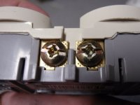
Brass color screws are Line (black) Silver screws are Neutral (white)
Don't try to switch power supplies, except on for the show and off after the show. There is too much of a delay to blink flash thru power supplies.
You say you cut the hot tabs.....did you cut the Brass tabs (hot-line-black) or the Silver tabs (neutral-white)
 
What the previous person is saying is that you Daisy chained your four relay outlets together on their neutral, which is correct, then you connected those four chained outlets to your feed outlets hot, this is NOT correct. Using the standard for green ground, white neutral, and black load will help keep you straight. Chain your relays neutrals to the feed neutral, chain the grounds to feed ground. Then the feed hot (black wire) goes to one of the terminals on each relay. The other terminal on each relay then goes to the hot on one outlet. At no point should a neutral connect to a hot.

I also agree with this wiring issue. We can see the miss wring based on the ground location. Align all ground terminal to the bottom and you will see the receptacle with the plug is wired differently.
 
FBXRN13GTYSUWPO.MEDIUM.jpgFU7UIKGGTXKH5L1.MEDIUM.jpg
This is the setup I used in the past. Just as the others said, change out that green wire with a white one then connect it to the white wire on the outlet you don't have mounted yet. On that same outlet a black wire connected to the black wire you already have connected will then go to supply power to each of your relays. Then use black wire to make the connections to the relays from each outlet. This will make things much easier especially when making future repairs. Break the tab only on the copper screw side and leave the tab intact on the silver screw side. Each relay will connect to a single screw on the copper side of the outlet providing 2 separate outlets as the picture you have depicts.
 
I broke the tab on the copper side. and I have wire I just used green. the drop cord had green,black,white wire I didn't know what color to use this is just to find out if it's right. ever single outlet including the non mounted on has the green wire connected to the silver side of the outlet and I left the copper side open for my relays to connect.
a friend of mine keeps trying to tell me white is hot and black is neutral but I think he's confused. I've got to get some ends to put on the wires I will use white wires in the end.
so the wire from the group of plugs needs to go to the left side also on the separate outlet. where does the white wire from the plug in need to go then?


Sent from my SM-S920L using Tapatalk
 
View attachment 38005View attachment 38006
This is the setup I used in the past. Just as the others said, change out that green wire with a white one then connect it to the white wire on the outlet you don't have mounted yet. On that same outlet a black wire connected to the black wire you already have connected will then go to supply power to each of your relays. Then use black wire to make the connections to the relays from each outlet. This will make things much easier especially when making future repairs. Break the tab only on the copper screw side and leave the tab intact on the silver screw side. Each relay will connect to a single screw on the copper side of the outlet providing 2 separate outlets as the picture you have depicts.
Thanks, I think i understand now. I just changed that one wire so this is right

post #47 now should be correct.

Sent from my SM-S920L using Tapatalk
 
Last edited:
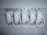
Thanks, I think i understand now. I just changed that one wire so this is right now?
6806c3d2376ba42bc642c1aec0f7e4f2.jpg


Sent from my SM-S920L using Tapatalk

The connections look right now. I would change the green wires to white (except for the ground wire on the first receptacle) and make sure you use black for the hot wires. It might keep you or someone else from electrocuting themselves. For standard house wiring, black is always the hot wire. Someone told me the way to remember is that black means death. I've never forgotten. Again this assumes your SSRs switch line voltage and not the neutral.
 
Last edited:
The connections look right now. I would change the green wires to white (except for the ground wire on the first receptacle) and make sure you use black for the hot wires. It might keep you or someone else from electrocuting themselves. For standard house wiring, black is always the hot wire. Someone told me the way to remember is that black means death. I've never forgotten. Again this assumes your SSRs switch line voltage and not the neutral.
alright I'm going to change them to white tonight.
So there more then one way to switch them on? I'm just trying to do it however needs to be done. again lots utube videos but Noone really goes into details on how to wire it up. guess they assume most understand this stuff more then I do..

Sent from my SM-S920L using Tapatalk

You're dealing with 120 AC, which can be lethal. For the safety of everyone around you, you shouldn't be doing this without a firm grasp of what you're doing. Right now, you're merely doing this based on a hodge-podge of youtube videos and a few random commentors who can't even assess your whole plan/devices.

Look at how easily the rest of us make mistakes in the 12v world. We get a puff of smoke when we mis-wire. At 120v, it's much worse.
Yes they can cause there are people who has done this same thing.. it's just Noone has posted detailed to how to hook it up. The reason why I posted to have other double check what I've done before snything is plugged in so nothing does smoke.

hooking a raspberry pi to ssr for christmas lights isn't new look on YouTube tons have done it just Noone goes into full details of the wiring they just say hey look at my lights.

Sent from my SM-S920L using Tapatalk
 
Thanks, so your supplying the relay line and power both from.the ssr right
I thought you only supplied from the relay for making it come on and off

Sent from my SM-S920L using Tapatalk

The neutral should come from the SSR along with the line. I show it with 1 neutral every receptacle because a single wire to all 8 receptacles may be too much load for one wire or one terminal point on the SSR.
 
The neutral should come from the SSR along with the line. I show it with 1 neutral every receptacle because a single wire to all 8 receptacles may be too much load for one wire or one terminal point on the SSR.
I had only seen it done with the one wire that seems be how everyone does it so the way you do it you feel gives you better power to each outlet.

Sent from my SM-S920L using Tapatalk
 
I used this SSR:
https://www.amazon.com/SainSmart-8-...id=1509927805&sr=8-6&keywords=sainsmart+relay

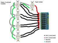
it only switches the line or neutral, not both. I chose to switch the line. I tried to draw out a rough diagram of how I did it. Again, I'm not a licensed electrician or anything of the sort, I'm a computer programmer so take it as you wish. If you have questions find someone who understands wiring AC outlets or take it to your local hardware store and ask them to "reality check" your setup before you plug it in.

I used black, white, and green wire as per standard use. my picture has different colors so you can see it.

ssr.png
 
The set up looks better. If you can, post the info of the ssr relays you are getting. This way we can draw an accurate wiring diagram to help out. I'm glad you are asking for help so that you can learn. That's what this hobby and fourm are all about.
 
I used this SSR:
https://www.amazon.com/SainSmart-8-...id=1509927805&sr=8-6&keywords=sainsmart+relay

it only switches the line or neutral, not both. I chose to switch the line. I tried to draw out a rough diagram of how I did it. Again, I'm not a licensed electrician or anything of the sort, I'm a computer programmer so take it as you wish. If you have questions find someone who understands wiring AC outlets or take it to your local hardware store and ask them to "reality check" your setup before you plug it in.

I used black, white, and green wire as per standard use. my picture has different colors so you can see it.

View attachment 38016
Okay, so the ground also needs to run from each outlet also? none ever showed a ground that i could see anyways so was wondering..
your red wire is how i planed to do mine just go from each channel on the SSR to the next one...
then the black from each channel on the SSR to each outlet for the 8 channels
 
The set up looks better. If you can, post the info of the ssr relays you are getting. This way we can draw an accurate wiring diagram to help out. I'm glad you are asking for help so that you can learn. That's what this hobby and fourm are all about.

this is the one i have on order and will be using to start with... Im thinking to switch to a USB one however but there all about the same right
https://www.amazon.com/gp/product/B0057OC5WK/ref=oh_aui_detailpage_o00_s00?ie=UTF8&psc=1
One thing i still not sure is driffrence from a 5v or a 12v one..
this is the usb one https://www.amazon.com/SainSmart-Ei...0a-20&linkId=1eec23eb8e74cef314d69cbb7216da82


i am one of those that say until you do something you will never know how to do something. i am a mechanic, have always worked on my own cars. i learned by watching and asking questions.. I wanted to learn HTML and i taught myself it by reading online.
 
Back
Top