HLS User Manual and Reference Guide - PDF
Getting HLS
Download and Installation
Download HLS
Download the software HLS_Install_**.zip from [1] and save it to your computer.
- Tip: One way to organize the downloaded versions is to create a folder named "HLS Versions" and save downloads there.
- Unzip the HLS_Install_**.zip and four files will be created in a folder named the same as the zip file. These four files are:
- DBGHELP.DLL
- ftd2xx.dll
- HLS.exe
- ipworks8.dll
Folder Hierarchy
Unlike a lot of software, HLS doesn't change your registry and isn't installed in a typical way. All that's necessary to get HLS up and running is to place the four files listed above into a folder and you are off and running. A little time spent on creating a foundation of folders to hold your copy of HLS will go a long way in keeping your computer organized and the files you will be creating logical and easy to find.
Note: Prior to version 16K, the HLS Program and Data all were contained within the HLS Application folder. Starting in version 16K, data can be set to any place you want. Your Documents folder, an external hard drive, etc. Follow the Moving HLS Data Directories page to separate data from application.
Wherever you decide to save HLS data, the following structure is suggested:
HLS
HLS\Backgrounds
HLS\Library
HLS\Music
When you create an HLS sequence, HLS will create a folder under your HLS folder with the sequence name.
HLS Installation
- Now that you have the foundation of folders created, copy the four files from the HLS_Install_**.zip version into your "HLS" folder.
- Now you are ready to run HLS.
- Note: If you are using Windows 7 you need to change the properties of the HLS.exe file to run as Administrator.
- Open HLS.exe and begin to sequence.
OS Specific Installation
Windows 7/Vista HLS Installation
Upgrading HLS)
Standard Upgrade
When you start up HLS, it automatically checks for the most recent version. If there is a new version, a window will open asking if you want to upgrade. If you choose yes, you will be redirected to the website to download the newest version.
- Simply download the latest version, unzip the files, and overwrite the old files with the new ones.
Upgrade Path for Skipped Updates
Due to the high rate of development of HLS, if a user is not monitoring the updates frequently, it is easy to fall several versions behind. If someone upgrades to the latest version from an older version, there is risk of data loss from the sequence files no longer being able to be opened.
To address this concern, there is an upgrade path that can be taken to move from older version to the newest version. Each time an upgrade step is made, any sequences that you want to keep should be opened in that step and saved before moving to the next step.
- Upgrading from a version less than 11E: Install version 11H [2]
- Open any sequence you wish to keep in version 11H and Save Sequences.
- Upgrade from 11H to the most current version. [3]
- Open and Save sequences again to have them fully updated.
Creating a Sequence
HLS Sequence Creation Wizard
HLS has a built in New Sequence Wizard which will walk you through the steps of creating a sequence. If you are attempting to create a new sequence but want to base it's setup on a previously created HLS sequence, follow the instructions on Using HLS Sequence Images.
Setting up the Sequence File:
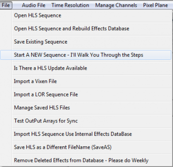
- To begin, open HLS and select the FILE menu, then choose Start a NEW Sequence - I'll Walk You Through The Steps (See Figure 0-1).
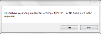
- HLS will ask if your sequence will use audio (Yes), or no audio (no) (See Figure 0-2).
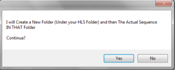
- HLS will ask for permission to create a folder for your new sequence under your HLS folder (YES) (See Figure 0-3).
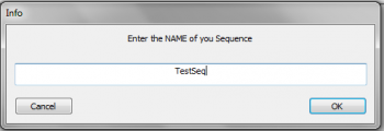
- You will then be prompted to provide a name for your new sequence (See Figure 0-4).
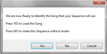
- HLS will then alert you that it is ready for your audio. (See Figure 0-5).
Setting up the Audio File:
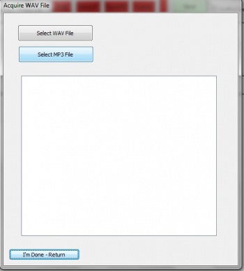
- A prompt will open asking you to select a WAV or MP3 file (See Figure 0-6).
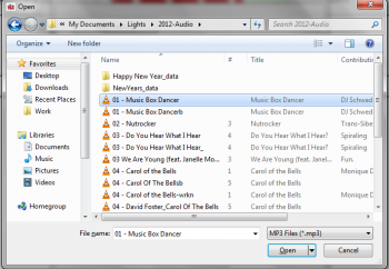
- Navigate to your music file and select it. In this example Music Box Dancer MP3 will be chosen (see Figure 0-7).
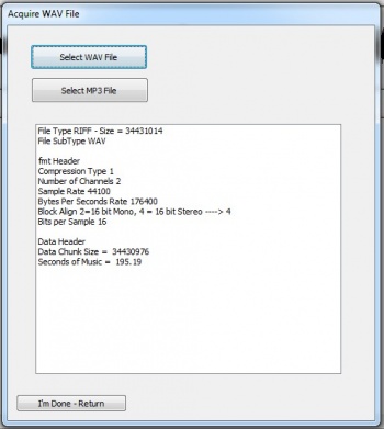
- After your music file has been chosen and processed, Figure 0-8 will appear.
- Click on the "I'm Done - Return" button. You should get a save confirmation message (See Figure 0-9).
Time Resolution)
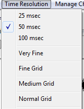
The Time Resolution must be set before you setup any channels. Once it has been set, you cannot change it again. The default time resolution is set for 50 milliseconds. You can also choose a 25 millisecond or 100 millisecond time resolution. The time resolution sets how frequently effect changes can occur on a channel.
- 25 msec: This provides 40 timing grid spaces for every second.
- 50 msec: This provides 20 timing grid spaces for every second.
- 100 msec: This provides 10 timing grid spaces for every second.
Simply click to select the time resolution you would like for your sequence.
The grid options on the menu adjust how "fine" the grid spaces are. This only affects what you see as you sequence and does not affect anything with the sequence itself. This can be adjusted at any time while sequencing.
- A higher grid resolution will result in more channels displayed on the screen at one time and more timing marks on display at one time, but the disadvantage is that the grid squares are smaller.
- A lower grid resolution will result in larger squares which are easier to see, but the disadvantage is fewer channels and timing marks on the screen at one time.
Channel Management
Setting up HLS Channels
Introduction
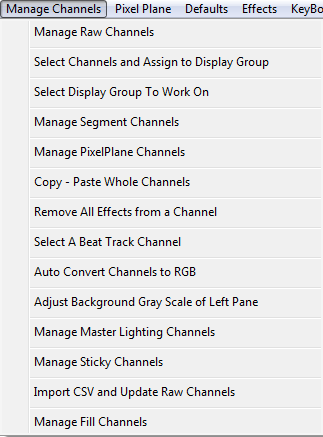
HLS Channels are controlled using the Manage Channels Menu at the top of the screen. See figure 3-1. While there are many functions on this menu, this document will mainly focus on the first option: Manage Raw Channels. Select this option to add and manipulate the raw channels associated with the sequence you are working with.
Important: If you plan to use a time resolution that is different than the default (50 msec), it MUST be set BEFORE you add any channels. Once you add channels, this time resolution CANNOT be changed.
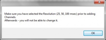
Next we will set up HLS Channels. Click on the Manage Channels tab at the top of the page and then click on Manage Raw Channels. At this point you will see a message reminding you to choose your time period resolution before you continue (see Figure 3-2). Next, click on the OK button.
Adding Basic HLS Channels
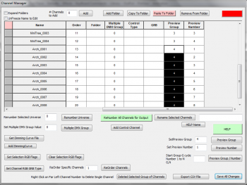
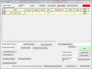
The Channel Manager screen will now as appear (see Figure 3-3). This is where we will add and configure HLS channels.
- HLS Channels are not the same as channels on a controller. HLS channels can represent a strand of incandescents or LED's, a "super string" of 3 light colors connected to the same object, a dumb RGB item, a single pixel, or a plane of pixels. This versatility is one of the features that sets HLS apart from some other sequencers.
- Output channel configuration is handled in the "Output" section of HLS and cannot be setup from the Raw Channel Manager.
To add channels:
- In the # of Channels to Add field, type the numeric value of number of channels to add.
- Click the Add button to create the channels.
Naming Channels
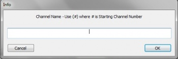
HLS will pop up a window asking for the common name for the channels (See Figure 3-4). You can enter anything in the blank and HLS will auto-number the channels, starting at 1. If you would rather NOT start at 1, you can input a different number in parenthesis. For example, to add channels starting with number 15, you could enter Chan(15) into the box. Hit Enter when complete.
Changing the Assigned Universe
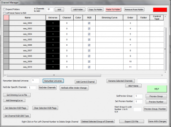
When adding channels, HLS automatically assigns them to Universe 0. Any channels assigned to Universe 0 will NOT output to controllers. If you'd like to, you can go ahead and assign channels to a universe. Or, if you prefer, you can do this when you are ready to set your channels up for output.
- In the example of Figure 3-5, 10 HLS channels have been added.
- To change them to Universe 1:
- Select all channels to change by clicking on the top channel (inside any box) and drag the mouse cursor down until all channels are selected.
- Enter the number one into the Renumber Selected Universe field.
- Click the Renumber Universe button.
- Note: Some channels will always be Universe 0. Channels like beat tracks, pixel planes, lighting channels, and segments are not designed for output. These types of channels will be discussed further in the guide.
Applying Colors to Channels
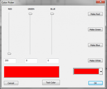
Setting a color for an HLS channel is important as it is the color that appears in the sequencer as you add effects and is also used in the Display Preview.
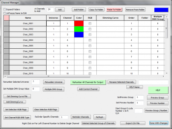
- In the top right corner, there is a color block. Click it to bring up the Color Picker (See figure 3-7).
- Once the Color Picker is open, you can easily set it to one of the more common lighting colors or you can click the drop down box in the bottom left to choose any color you like.
- Once you have selected a color, click OK to use it.
- Right-click in the Color column of any channels you want to be demonstrated with that color. (See figure 3-8.)
- Hint: To save time, choose one color at a time and set all same-colored channels at the same time before switching to another color.
Simple Renaming
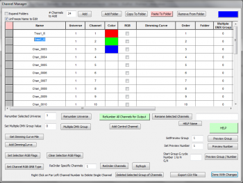
Generally, you won't want to keep a bunch of channels with the same name. Or you may want to make minor changes to names as you go along. In the example shown in Figure 3-9, the first channel has been renamed and the second channel is in process of being renamed.
- First, you MUST check the UnFreeze Name to Edit box in the top left.
- Once names are unlocked, click into the field and type a new name.
- Group renaming, using folders, moving items, and other complex tasks are in the Advanced Channel Management section.
Advanced Channel Management
Introduction
The Manage Raw Channels window is truly a powerful tool. In this document, we will explore some of the more advanced features of the channel manager. Something that everyone needs to know before doing anything with channels is, SAVE YOUR SEQUENCE BEFORE YOU MAKE CHANNEL CHANGES. When managing raw channels, there is no cancel or undo. What happens, happens. If you save your sequence right before working with channels, if something goes wrong, you can always restore to the previous backup.
Grid Columns and What They Mean

There are a number of columns in the Raw Channel window. Figure 3-10 shows a subset of those columns. (Some columns are out of view.)
- Left-most Gray Square: This is a selection box. You left-click in here and the square becomes green. That channel (and any others you left-click on) is selected and can be moved into a folder or deleted.
- Name: This field shows the name of the channels.
- Universe: A numerical value from 0-5000. Any channels in universe 0 will never be displayed.
- Color: This field is set to the color of the channel.
- RGB: This checkbox is checked when a channel is an RGB lighting element or pixel.
- Dimming Curve: This field is to set a dimming curve for the channel.
- Order: This field is used to adjust the DISPLAY order of the channels.
- Folder: The number of the folder that a channel is assigned to.
- Control Type: This is used with animation effects and trigger events.
- GRB: Used when the order of the RGB is different from Red-Green-Blue.
- Preview Group: This group number defines what Preview Group the channel belongs to.
- Preview Number: This is the channel number for the assigned display group.
Advanced Renaming Channels
When adding a bulk group of channels, HLS will ask for a base name to start with, but you most likely will want to customize the names for your purpose. You can rename individual channels, rename using the bulk renaming utility, and even create names in excel that you paste into the Channel Manager.
Rename Individual Channels:
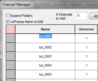
To rename individual channels, you must first open the Channel Manager (Manage Channels -> Manage Raw Channels). See Figure 3-11.
- Check the box to Unfreeze Name to Edit.
- Click on the channel you wish to rename.
- Highlight the old name and type in the new name.
- When done, Click Done with Changes.

Bulk Channel Renaming:
There are two methods of bulk renaming built into HLS. There is a help file for this by clicking HELP Name in the Channel Manager.
Method One:
- This is the more straight-forward and basic method of bulk renaming.
- Highlight the cells you wish to rename
- Formula: Name_(StartingChannelNumber)
- This will rename channels with "Name" shown except replace (StartingChannelNumber) with a sequential number starting at the number specified.
- Examples:
- "MTString_(1)" will produce MTString_0001, MTString_0002, etc.
- "Yard_(15)" will produce Yard_0015, Yard_0016, etc.
Method Two:
- This method is likely to be used when renaming large groups of pixels or strings.
- Highlight the cells you wish to rename
- Formula: @NumberOfPixels, Name(*StartingStringNumber)_%
- This will rename channels with "Name" shown, followed by the value of "StartingStringNumber", and then counting UP until reaching the "NumberOfPixels" value.
- Once reaching the "NumberOfPixels" value, the value of "StartingStringNumber" will increment by 1, and the "NumberOfPixels" will start counting upwards from 1 again.
- Example: A pixel megaTree with 32 strings composed of 42 pixels each:
- @42,MTString(*1)_% will rename channels with values of MTString01_0001 to MTString32_0042
Relevant Video Tutorial: Pixel Based Mega Tree
Reordering Channels

The Order column is a numeric value ordering the channels from 1 to the last channel.
To ReOrder channels:
- Select the channels you wish to move.
- In the ReOrder Specific Channels field (See Figure 3-13), enter a number that does not conflict with existing channels and then click ReOrder Channels.
- Once the channels have been ReOrdered, click Refresh After Order Change to update the Order column.
- Example: To move 5 channels from the beginning to the end:
- Highlight the five channels to move.
- In the ReOrder Specific Channels field, enter a number that is higher than the last channel's Order number.
- Click ReOrder Channels.
- Click Refresh After Order Change.
- Example: To move 5 channels from the bottom to the top:
- Highlight all channels EXCEPT the five channels to move.
- In the ReOrder Specific Channels field, enter a number that is higher than the last channel's order number.
- Click ReOrder Channels.
- Click Refresh After Order Change.
Using Folders
Create a New Folder:
- Open the Channel Manager (Manage Channels -> Manage Raw Channels).
- Click the Add Folder button on the top toolbar. (See Figure 3-14).
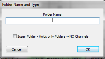
- A dialog box will open asking for a Folder name. Type name and press OK. (Se Figure 3-15).
- Note: A Super Folder contains only folders. Check this box if you wish to create a "folder of folders". This would be used for channel organization.
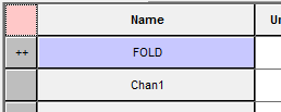
- Once entered, the folder will appear at the top of the list of channels and have ++ on the left-most square to identify it as a folder. (See Figure 3-16).
Moving Channels In/Out of Folders:


- Highlight the channels you want to add to a folder.
- Press the Copy to Folder button.
- This will turn the left-most square GREEN for selected channels.
- Tip: You can also select channels by left-clicking on the square to turn it green.
- Once all channels are selected (left-most square green), press the Paste to Folder button. This will turn from red-to-green. (See Figure 3-17, 3-18).
- Click on the left-most square of the folder you want to move the channels into. This will move the channels into the desired folder.
Remove channels from a folder:
- Click the folder name to expand the items.
- Select the channels to remove by clicking the left-most square and turning it green (or, highlighting rows to remove).
- Press the Remove from Folder button.
Opening and Closing Folders:
- To open a folder, simply click on the name of the folder.
- To close a folder, click on the name of the folder.
- To open ALL folders, click the Expand All Folders checkbox.
VIDEO: Joe describes folders and folder management
Copying Channels
Copying channels requires the use of both the main sequencing window and the channel manager. First, you must use the Channel Manager to add the new channel(s) you will be copying into.
Once that is done, you will have to add the new channels and the channels you will be copying from into the same Display Group.
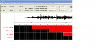
To copy one or more channels click on the channel and asterisks will appear to the left of the channel name (see Figure 3-19. The click again on the channel to select it. Then Select the Manage Channels tab and choose Copy - Paste Whole Channels. You will then be prompted to Click on the Channel to Paste To.
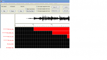
To copy multiple channels click on the first channel to be copied and asterisks will appear to the left of the channel name. The without clicking move your mouse down to include all of the channels you would like to copy (see Figure 3-20). Asterisks will appear to the left of the channel to be copied. Once you have selected all of the channels to be copied click again on the last channel to be copied to select all of them.
Then Select the Manage Channels tab and choose Copy - Paste Whole Channels. You will then be prompted to Click on the Channel to Paste To. Note that if you are copying a number of channels you will have to have that many to paste to.
Deleting Channels
- To remove channels, open the Channel Manager (Manage Channels -> Manage Raw Channels).
- Highlight the channels to delete by clicking and dragging into the data fields.

|
| Figure 3-21: Click the Delete Selected Channels button. |
|
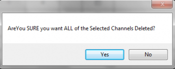
| Figure 3-22: Confirm you wish to delete by clicking yes. |
|
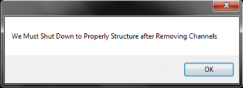
| Figure 3-23: HLS will prompt to shut down to
update its configuration. Click OK. Then OK again. |
Program Help File
HLS now comes with a detailed help file. This file is reproduced here to help so that you can have the channel manager open and look at the help file at the same time.
Expand Folders - Shows ALL Channels - Expands ALL Folders
Unfreeze Name to Edit - Clicking Names causes Folder Events to Occur - To Edit Name - Check This
Add Channels - This is the Number of Single Channels or Pixels (Pixels will be 3 Channels on Output)
Add Folder - Folders contain your Channels. A Super Folder can contain multiple Folders
Copy to Folder - High lite several rows of Channels to assign to a Folder - this will make Cell 0 Green - Ready to Assign
Clicking on the First cell of a Row (Expand Channels OFF) will also select Channel to be assigned to a Folder
Paste to Folder - When Channels have been selected - Press this button - Turning it Green indicating Left Mouse Click on ++ of Folder will assign Channels to that folder
Remove from Folder - High lite several rows of Channels to Remove from a Folder - Press button to perform operation
Colored Cell in Upper Right Corner - Color Selection Control
In Grid - L click in first column to select Channel for Folder Assignment or Removal from Folder
In Grid - R click first column to DELETE channel or Folder
In Grid - R click dimming curve to assign
Renumber Select Universe - Used to assign Output Universe - High Lite Channels and assign number specified
Set Multiple DMX Group - used with 4096 channels DMX Devices - Enables Universe of 4096 instead of 512
Get Dimming Curve - Select Dimming Curve to Bulk Assign
Add Dimming Curve - High lite channels then Assign Dimming Curve Selected by 'Get Dimming Curve'
Set/Clear RGB - High lite Channels and Set/Clear RGB Flag
ReOrder Channels - High lite Channels - Assignment starts at Number specified. ReOrders Channels in List
Renumber All Channels for Output - This will Assign the correct Channel Numbers based on Order and RGB - Universe must be Non-Zero
Add Control Channel - Assign Triggers, Animation Mouth, Words, etc
Rename Selected Channels - Press HELP to see Macros that can help Create Unique Names
Preview Group - High lite Channels and Assign Preview Group to selection
Preview Number - High lite Channels - State Starting Chan Number - Each Channel is Incremented
Start Group G cycle Number 1 to N - G,N .... Enter Group Number followed by Number High Lite Channels - Groups starts at G with Chan Number starting at 1. When Chan Number hits N - G is Incremented and Chan Number starts at 1
Delete Selected Group of Channels - High Lite channels and Delete with this button
Export CSV - Creates a CSV file containing all of your Channel Information
RGB Channels
Introduction to RGB
RGB lighting, both dumb and smart pixels, have added a large amount of complexity and channel counts in displays. HLS is very advanced in handling RGB channels. This section of the wiki will discuss setting up channels, converting multiple channels into one, and how to use the RGB features for other display items.
Adding RGB Channels

To add RGB channels, first, open the Channel Manager (Manage Channels -> Manage Raw Channels).
- Add the number of RGB channels that you will need.
- Note: Add the number of RGB "whole" channels you need, not the individual channel numbers. HLS will recognize that RGB channels contain 3 real channels automatically. So, if you have 50 pixels, add 50 channels, NOT 150 channels.
- Select the channels that will be RGB by clicking and highlighting them.
- Click the Set Selection RGB Flags to convert the channels to RGB. (See Figure 3-24)
- Assign the channels to a universe that is greater than zero.
- Click Renumber All Channels for Output to reconfigure the channel usage (i.e., 3 channels per RGB channel).
- If your channels have a GRB order, click the Set Channel RGB GRB Type button.
Converting 3 Red, Green, and Blue Channels to one RGB Channel
Even when you don't have actual RGB strings, but are using "Mega Strings", or, strings composed of multiple strands of lights, you can make use of the RGB Channel abilities in HLS to reduce your channel count. For example, a tree with red, green, and blue strands of lights could be classified as ONE RGB channel rather than three individual channels.
Another example when this may come in handy is when you have imported a sequence from Vixen or LOR which contains three separate RGB channels that you now want to combine into one.

To convert three R, G, B channels into one:
- Open the Channel Manager (Manage Channels -> Manage Raw Channels)
- Verify that the three channels you wish to convert are setup properly. (See Figure 3-25)
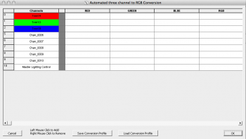
- Open the Converter for RGB (Click Manage Channels -> Auto Convert Channels to RGB. (See Figure 3-26)
- Locate the three channels you wish to convert.
- To move channels, Left-Click in the channel list, then Left-Click in the RGB section you want to move the channel. It will become "grayed out" when it has been moved and cannot be selected.
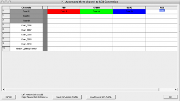
- Place the Red Channel in Red, Green Channel in Green, and Blue Channel in Blue. (See Figure 3-27)
- Click into the RGB column to name your newly created RGB Channel.
- Note: If you make a mistake, right-click the channel to move it back to the Channel list.
- Once all channels have been converted, click OK.

- A dialog will open with information about how many channels have been converted. (See Figure 3-28)
- HLS will then shutdown to update channel configuration.

- Open HLS and open the Channel Manager to see the newly converted channel(s). (See Figure 3-29)
To Make the RGB Conversion Automatic:
- When you import multiple sequences from another program which have the same channel setup, you can automate the conversion process of R, G, B into one RGB.
- Open the first sequence and follow the conversion steps above.
- Once the conversion is complete, click Save Conversion Profile.
- Type a name for your saved Conversion Profile and click Save.
- Click OK.
- Open the next sequence to convert.
- Click Load Conversion Profile
- Select the file to load and click Open.
- Once conversion is complete, click OK.
Using RGB Channels to Reduce Multi-Color Channels by 2/3
Red, Green, and Blue "mega strings" aren't the only grouped strings that can benefit from the RGB single channel conversion. If your colors are different from those, you can still use the RGB channel to reduce channel count by 2/3. As an example, imagine a Mega tree with 16 strings of red, white, and blue lights (48 strings total). If those mega strings were converted to single RGB channels, the channel count would go from 48 to 16.
- Follow the conversion steps above to convert the multiple channels into RGB channels. Except this time, Red goes to red, WHITE goes to green, and Blue goes to blue.
- When programming, use red effects for the red lights, blue effects for blue lights, and GREEN effects to control the white lights.
- If you program white in the RGB channel, then all three colors (red, white, and blue) would be on.
- Think of the RGB string as three channel control rather than only red, green, and blue control.
Configuring Display Groups
Introduction to Display Groups
Display Groups are one of the most powerful features of HLS. It is important to understand what they are and the purpose they serve. In basic terms, a Display Group is a group of channels that will be displayed in the main sequencing window so you can "work" with them (i.e., add effects, etc.). Channels can be contained in more than one Display Group. Groups make it possible to show and work with a subset of the channels.
- Note: Display Groups are NOT the same as Preview Groups. Display Groups DISPLAY channels in the sequencing window. Preview Groups are used with the PREVIEW window to help visualize how channels will be physically represented in the display.
Some examples of how Display Groups can be used:
- Global Grouping:
- All: A group containing every channel.
- Display Object Grouping:
- MegaTree: A group containing all of the MegaTree channels.
- Roofline: A group containing the roofline channels.
- Arches: A group containing the channels used in arches.
- Windows: Group containing windows.
- Physical Location Grouping:
- House: All channels on the house.
- Yard: All channels in the yard.
- Left, Middle, and Right: Three groups that could be setup to break the display into left, middle, and right sides.
- Color Grouping:
- Red, Green, Blue, and White: Groups could be setup to work with specific colors.
- These are just SOME examples of how groups could be used. Your imagination is the limit!
Assigning Channels to Display Groups
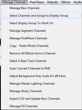
To begin working with groups, first, channels must be assigned to a Display Group.
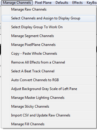
- Click Manage Channels -> Select Channels and Assign to Display Group. (See Figure 3-30)
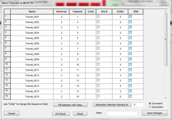
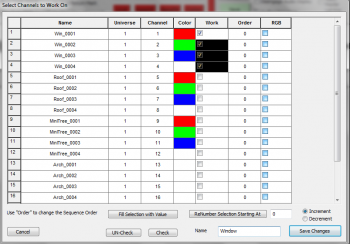
- The Select Channels to Work On screen will appear (See Figure 3-31).
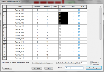
- Select the channels you wish to assign to your group by clicking and dragging to highlight the channels.
- Click on the Check button to place a checkmark in the Work column. You are telling HLS which channels you want to "work" on.
- Type in a Name for your new Display Group in the lower right-hand text field and select Save Changes. (See Figure 3-32)
- Note: You can also choose channels individually to include in a group by manually clicking the Work checkbox for each channel.
Select a Display Group to Work On
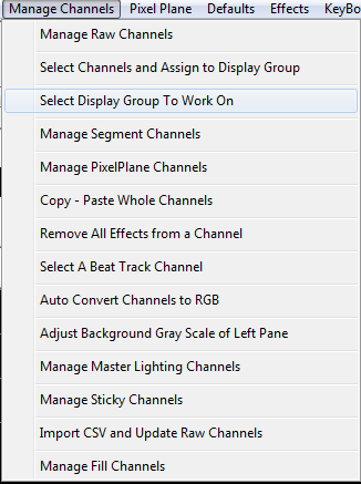
To display the newly created Display Group, HLS needs to know that you want to work on it.
- Select Manage Channels -> Select Display Group to Work On. (See Figure 3-33)
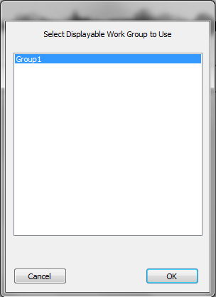
- Figure 3-34 will appear. Select the Display Group you wish to work with and click OK.
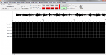
- The Sequence editor window will appear and the channels in your Display Group will now be ready for work (See Figure 3-35).
Managing Display Groups
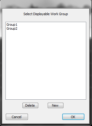
To add a new display group:
- Click Manage Channels -> Select Channels and Assign to Display Group.
- Figure 3-36 will appear. Click New to create a new display group.
- Follow directions above to select channels.
To remove a display group:
- Click Manage Channels -> Select Channels and Assign to Display Group.
- Figure 3-36 will appear.
- Highlight the Display Group you wish to remove and Press Delete.
To Modify a Display Group:
- Click Manage Channels -> Select Channels and Assign to Display Group.
- Figure 3-36 will appear.
- Highlight the Display Group you wish to modify and select OK.
- The Select Channels to Work On window will appear showing all channels in the group.
- Click Modify List to display all other channels.
- Check and Un-Check the Work column to add or remove channels from the Display Group.
- When done, click Save Changes.
Sticky Channels
HLS allows the user to set up to three "Sticky Channels". These are channels that can be displayed at the top of the sequencing window (in place of the Audio Oscilloscope). They maintain their position when scrolling through channels in your sequence. This can be useful in setting beat tracks that are always at the top or for lining up sequencing effects with another channel.
VIDEO: Joe describes sticky channels in his 2013 Intro video
To Set Sticky Channels:
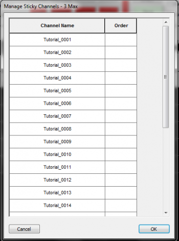
- Click Manage Channels -> Manage Sticky Channels.
- This will open the Manage Sticky Channels window which will show all of your channels (See Figure 3-37).
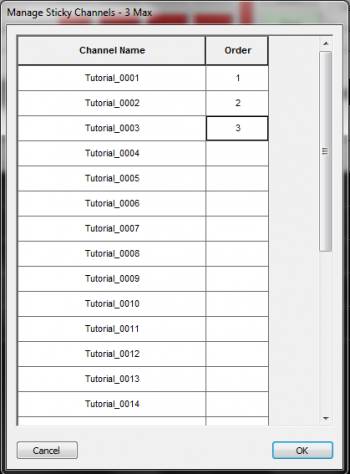
- To set a channel as a Sticky Channel, Click in the Order column next to the channel name and enter a number (1-3). (See Figure 3-38)
- Once you have numbered the Sticky Channels, Select OK.
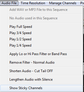
- To toggle between Sticky Channels and the Audio Oscilloscope, click Audio File -> Show Sticky Channels (See Figure 3-39).

- The Sticky Channels will now be at the top of the screen (See Figure 3-40).
Segment Channels
Segment channels allow you to assign multiple channels to a single HLS Channel. As you add effects, modify them, or delete them on the segment channel, all the channels in that segment are affected. Segments add some macro control of your display elements and are especially useful for pixels or face animations.
VIDEO: Joe describes Segment Channels and gives examples of their use in his 2013 Intro video
Examples:
- Multiple pixels or channels assigned to mouth movements.
- An arch of pixels, with groups of pixels assigned to segments.
- Assigning a specific color of channels that are on mini-trees to one segment.
Creating Segments for Existing Channels:
- Open the Segment Channel Manager (Manage Channels -> Manage Segment Channels).
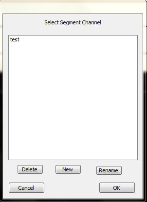
- Figure 3-41 will appear. Click New to create a new Segment.
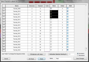
- Figure 3-42 will appear. Select the channels you wish to assign to a segment, click "check", name the segment, and click OK.
- Continue to add segments as needed.
- Tip: You can also rename segments through the Segment Channel Manager (as of 16K).
Assign Segments to a Display Group:
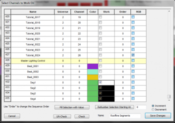
- Create a new Display group, but only add the newly created segments to the group.
- Note: The Segment Channels will appear with a green color. See Figure 3-43.
- Name the group.
- Set the group to Display in the sequencing window.
- Add effects to the segments, which will show up in all channels contained in the segment.
Out of Sync Effects:
- If a channel composed in a segment already has effects in cells, those points will be "grayed out" in the Segment view.
- You will be unable to modify those effects in the Segment view. This protects those effects from being damaged while editing a full segment.
- To be able to adjust the entire segment area, you must set the display group to view the channel(s) that contain effects at that point in time and remove them.
- Once you have applied effects in segments, you can go back in to the individual channels and adjust them if needed.
Video:
Display Preview
Creating a Display Preview
Preparing Channels for Preview
- Ensure that channels are properly added to the sequence, rgb channels are identified, and colors are setup in the Channel Manager.
- See Setting up HLS Channels for more detailed instructions.
- See Setting up HLS Channels for more detailed instructions.
- Assigning Channels to Preview Groups and Preview Numbers:
- Open the Channel Manager. The last two columns in the channel listing are Preview Group and Preview Number. These two numbers allow you to form multiple Preview Objects, such as MegaTree, RoofLine, Window, Arch, etc. and assign a pair of numbers (Group and Number) to them. They can range from 1-1000. Anything set as 0 will not be displayed.
- Preview Group: This number groups channels together into one Preview Object. For example, an arch can have 8 segments with each segment assigned to Preview Group 3.
- Preview Number: This corresponds to each channel in a Preview Group.
- Assign Preview Groups and Preview Numbers for each of your channels. (This can be done manually by left-clicking into the fields and entering numbers, but there are ways to do it quicker.)
- Using the left mouse button, click in the first item of a Preview Object and select down the channel cells until reaching the last channel of the object.
- In the Set PreviewGroup field, enter the Preview Group value and click Preview Group button. This will set that value for all items in the Preview Object.
- To set the PreviewNumber values from 1 to the highest selected cell, make sure Set PreviewNumber is set to one, then click the Preview Number button.
- To set Preview Groups and Preview Numbers for large sets of channels that contain the same number of components (for example, pixels):
- Determine the number of components in the set of channels (for example, 42 pixels in a string, a total of 16 strings).
- Select all channels to be grouped.
- In the Start Group G cycle field, enter: 1,42. This would start with group 1, and number 42 components. Then, would move to group 2, etc, all the way to group 16, preview-number 42.
- Open the Channel Manager. The last two columns in the channel listing are Preview Group and Preview Number. These two numbers allow you to form multiple Preview Objects, such as MegaTree, RoofLine, Window, Arch, etc. and assign a pair of numbers (Group and Number) to them. They can range from 1-1000. Anything set as 0 will not be displayed.
- The image shows an example of an arch with 8 segments that has been selected and then assigned a Preview Group and Preview Numbers. It is assigned Preview Group 4 since the previous display element (a mini tree) was assigned group 3. Groups do not have to be in sequential order.
Assign Channels to a Display Group
- To be able to display, draw, and preview channels, they must be assigned to a display group.
- Click Manage Channels, then select Select Channels and Assign to Display Group.
- Left-click into the Work column and select the first channel to be added to a Display Group. Then, Click and drag, highlighting all cells to be part of the Display Group.
- Check the cells selected by clicking Check.
- Add a Name for the Display Group, then press Save Changes.
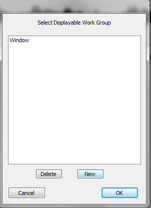
- In the picture example, a Display Group named "Window" is being created for the four highlighted elements that outline a window.
- Continue creating Display Groups for all elements. When adding additional Display Groups, a window will prompt to either edit or create a new Group. Click "New" to continue creating groups.
Creating the Preview Window
- Warnings and Limitations:
- All images in the Preview must be in bitmap format (extension of .bmp). Windows paint will allow conversion of files into this format.
- Image resolution cannot be larger than your screen. Doing so could lead to you not being able to access the commands as the image would cover your entire screen.
- When editing a new preview, immediately move the Edit Preview Toolbar to a bottom corner of your screen. This will help prevent the preview window from covering the toolbar once it has been re-sized.
- Tip: If your Toolbar does become hidden behind a preview window, press 'Z' to restore it.
- The Preview window cannot be resized during editing. Once it is set, it is set. However, it can be resized when viewing lights in a sequence.
- Preparing a Background Image:
- Open your house image in an image editing program (MS Paint will be sufficient. Gimp[4] is another choice).
- In MSPaint, you can click Properties to determine the size of your image. You can use "resize" to change the size.
- Once the image has been resized, save it as a bmp file in HLS/Backgrounds.
- Tip: If you save the image as filenameWWWxHHH.bmp, where WWW is the width in pixels and HHH is the height in pixels, it will make it easier to remember the aspect when importing into HLS.
- Editing a new Preview:
- Select Preview on the menu bar, then select Edit New Preview.
- Move the Edit Preview Toolbar to the bottom corner of your screen.
- On the Edit Preview Toolbar, select Set Resolution.
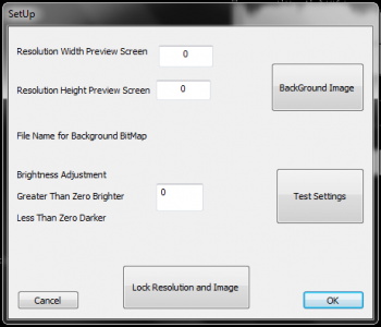
- This will open the Setup window, as shown:
- Using the Setup Window:
- Set the resolution width value to your display image.
- Set the resolution height value to your display image.
- Click the Background Image button and select your display image.
- Adjust brightness, if desired (negative numbers make it darker).
- Test settings when you make changes.
- Once satisfied, select Lock Resolution and Image to finalize display preview. A warning will open asking for confirmation. Click Yes.
- On the Edit Preview Toolbar, select Pick Preview.
- Select New, and name your Display Preview.
- Once done, select Save and close Preview Toolbar. You will be asked to confirm. Click Yes.
- Managing Multiple Previews:
- More than one Preview can be setup.
- To choose the one you want, simply click Preview -> Edit New Preview -> Pick Preview -> Select your choice, and click OK.
- You can then draw and manipulate the selected preview file.
Placing channels onto the Preview window
- With HLS, you draw onto the display window first, then assign channels/groups to the drawing.
- Some keyboard and mouse commands are fairly standard across various drawing components:
- Z - If preview window covers toolbar, pressing Z should bring the toolbar back into focus.
- ESC - Aborts the current action.
- BACKSPACE - This functions as an Undo, stepping one step backwards with each press.
- SPACE - This completes the drawing operation once your object has been defined.
- Left-click on canvas - This begins drawing a segment and ends drawing a segment.
- Right-click on canvas - This begins drawing a segment at the exact point previously stopped.
- When drawing elements, the "active" type of drawing being done will be in green, while all others are in red. In the example picture, "Line" is green because it has been selected.
- To Move display objects, left-click the move square for the object, then drag it in the display window.
Drawing Line Objects
- Line objects could be: roof lines, window frames, doorways, or any other display object composed of straight lines.
- Select the Line button on the Preview Toolbar to begin drawing a line item.
- Left-Click the beginning point.
- Move the mouse to the ending point, or the point where the line needs to turn.
- Press the left mouse again to complete the line segment.
- To draw an additional line starting at that exact stopping point, right-click and move to the next stopping point.
- Left-click the mouse to stop drawing that segment.
- Continue until complete. BACKSPACE will step back in the drawing.
- Once completed, press SPACEBAR to complete the line drawing.
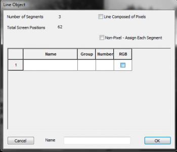
- A Line Object window will open with statistics about the drawing.
- For Standard Christmas Lights:
- If each line segment is it's own channel, select the "Non-Pixel - Assign Each Segment" box. Otherwise, do not check any boxes.
- Click in the Name field to select the appropriate channel(s) for the line and any relevant segments.
- Assign a name to the Preview Object.
- Click OK, OK to complete the channel assignment.
- For Pixels:
- Select "Line Composed of Pixels" and enter number of pixels in the line.
- Click in the Name field to select the pixels for the line.
- Select the first pixel and click OK.
- Assign a name to the Preview Object.
- Click OK, OK to complete channel assignment.
- Note: "Assign Channels in Reverse" is used if your pixels are running from right to left (for example, if power is distributed from the center).
- Video Tutorial [5]
Drawing Triangle Objects
- Triangle objects could consist of mini-trees, flood lights, or other objects.
- Select the Triangle button on the Preview Toolbar to begin drawing a triangle object.
- Left-Click the beginning point.
- Move the mouse to the second point and left-click. HLS will automatically complete the triangle shape.
- BACKSPACE will step back in the drawing.
- Once completed, press SPACEBAR to complete the triangle drawing.
- A Triangle Object window will open with statistics about the drawing.
- For Standard Christmas Lights:
- Click in the Name field to select the appropriate channel for the triangle.
- Assign a name for the Preview Object.
- Click OK, OK to complete the channel assignment.
- For Pixels:
- Select "Triangle Composed of Pixels" and enter number of pixels in the field.
- Click in the Name field to select the pixels for the triangle.
- Select the first pixel and click OK.
- Assign a name for the Preview Object.
- Click OK, OK to complete channel assignment.
Drawing Arch Objects
- Arch objects can consist of a strand of pixels or regular light segments.
- Select the Arch button on the Preview Toolbar to begin drawing an arch object.
- Left-click to begin drawing and left-click to end drawing.
- Once complete, press SPACEBAR to finish.
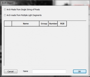
- An Arch Object window will open giving a choice to use a single string of pixels or multiple light segments.
- For Multiple Light Segments:
- Select "Arch made from Multiple Line Segments".
- In the box that appears, enter the number of segments contained in the arch.
- Click each name field in the table to chose the channels that make up the arch.
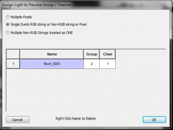
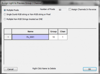
- Generally, you should chose "Single Dumb RGB string or Non-RGB string or Pixel".
- Click in the name field and select the appropriate channel.
- Click Ok. Continue doing this for all arch segments.
- Assign a name for the Arch Object.
- Click OK, OK to complete the channel assignment.
- For Pixels:
- Select "Arch made from a single string of pixels" and enter number of pixels in the field.
- Click in the Name field to select the pixels for the arch.
- Select the first pixel and click OK.
- Assign a name for the Arch Object.
- Click OK, OK to complete channel assignment.
- Video Tutorial for Arches[6]
Drawing MegaTree Objects
- A MegaTree can be composed of single color strings, mega-strings, dumb rgb strings, or pixel strings. The orientation can vary from up and down to make a pie shape, up and over, run from bottom to top, run from top to bottom, etc. It's important to understand how HLS can represent mega-trees when planning the physical display.
- HLS will always draw a megaTree as a 360° tree. The orientation will always start with the first strand at the 9 o'clock position and work in a Counter Clockwise direction. The strings must run in one direction: bottom-top or top-bottom. Default is Bottom to top. To go the other direction, select "Run in reverse" when assigning channels.
- Drawing a MegaTree:
- Open the Preview and load or create a Preview window.
- Select Tree from the menu and left click to start drawing. Left-click again to end drawing.
- Press SPACEBAR to complete drawing tree.
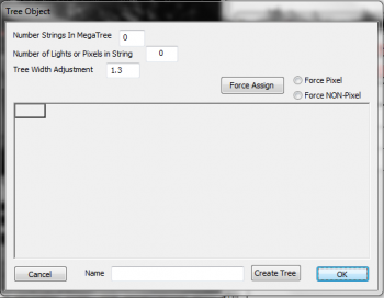
- The Tree Object window will appear.
- Single Color megaTree:
- Once tree is drawn, enter data into the Tree Object window to assign channels to the tree.
- Enter number of strings, and number of bulbs in each string.
- At the bottom of the window, name the tree, and click Create Tree.
- Select the first position on the tree and select the first string. Click OK.
- Select "Force Non-Pixel", and press "Force Assign". This will assign each additional string to the next position on the tree (As long as they are all in sequential groups).
- Click OK, OK to save.
- Pixel MegaTree:
- Before drawing tree, begin by setting up pixel strings on a Pixel Plane.
- Once tree is drawn, enter data into the Tree Object window to assign channels to the tree.
- Enter number of strings, and number of pixels in each string.
- At the bottom of the window, name the tree, and click Create Tree.
- Select the first position on the tree and select the first node on the first string. Click OK.
- Select "Force Pixel", and press "Force Assign". This will update all other points on the tree to reflect the strings previously setup.
- It is at this time to select "Run in reverse" if your strings go from top to bottom.
- Click OK, OK to save.
- How to handle trees that are 180°, 270°, etc.:
- HLS always makes a tree 360° To use a different angle, you must set the strings that are unwanted to not be displayed. You do this by assigning their Preview Group to 0. Then, do not assign physical channels to them. This allows other tree angles to work both in the preview and the physical display.
- HLS always makes a tree 360° To use a different angle, you must set the strings that are unwanted to not be displayed. You do this by assigning their Preview Group to 0. Then, do not assign physical channels to them. This allows other tree angles to work both in the preview and the physical display.
- Video Tutorial [7]
Drawing Custom Objects
- Custom objects are free-form drawings that can take on any shape. Some examples would include candy canes, snowflakes, custom light objects, etc.
- Drawing a Custom Object:
- Open the Preview and load or create a Preview window.
- Select Custom from the menu and left click to start drawing. Left-click again to end drawing.
- Press SPACEBAR to complete drawing.
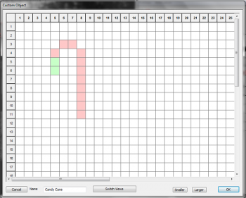
- The Custom Object window will appear.
- Drawing and Assigning Channels to Custom Objects:
- Begin drawing the object in the window. Left-clicks fill in a square. Left-click again to remove.
- Right-click a square to assign a channel.
- An unassigned square will be red; a square with an assigned channel will be green.
- Name the custom object and hit OK.
Drawing Mega-strings as one display object
- Setting up "mega-strings" as a single display item:
- Mega-strings are up to four strands of single-color lights that operate as one, such as a window outlined in R,G,B,W).
- Assign colors as normal. Place all colors into the same Preview Group and assign Preview Numbers.
- Select Manage Channels -> Set Display Group to Work On, then select your mega-string display group and select OPEN.
- This will open the channels in the sequence window.
- Open Preview
- Draw Object as described in previous sections.
- Once you press SPACEBAR, Assign lights to the preview, as seen in above picture.
- Select "Multiple Non-RGB Strings treated as ONE".
- Press "Add Another Channel" until you have the number of channels for your megastring (maximum 4).
- Assign the channels to the preview.
- Joe's video on mega-strings: [8]
How to "Draw Once, Use Everywhere"
- The value of the Preview is truly realized by setting it up once, then using it for all of your sequences. You can do this through the Display Groups.
- Always have ONE display group per element that is never duplicated elsewhere. The number goes to 5000, so feel free to space it out if needed.
- When opening the preview, simply "Pick Preview" to select a preview you have already set up.
Stepping Through a Sequence with Display Preview
- It is possible to step through a sequence using the display preview frame by frame.
- Tip: To use these commands, the main window GRID must have "window focus", not the preview window. So, the preview window stays visible on top, but you click the main window to give it "focus".
- On the top menu, select Preview->Select Preview Control File and select the preview file you want to use.
- Check "Sigle Step" and "Display Preview" checkboxes.
- Use the Right Mouse on the Ruler to set your RED marker.
- With the GRID in focus (NOT the Preview Screen):
- ZERO key will start the Preview Time line at the RED Mark.
- NINE key will advance the time tic by one.
- EIGHT key will decrement the time tic by one.
Sequencing Channels and Adding Effects
Creating Basic Effects
Introduction to Sequencing in HLS
Sequencing in HLS works by adding effects to lighting channels at specific time intervals to coordinate the lights with a set peice of music. HLS is different than other sequencers in that it moves beyond the idea of controlling individual channels and individual moments in time. While that can still be done, HLS is most powerful in it's use of macro-level control.
- RGB channels can be controlled without concern with the color levels of each underlying channel.
- Pixels can be grouped into Pixel Planes where complex effects can be as simple as drag and drop without having to think about things on a channel level.
- With HLS, sequencing thousands of channels becomes quite manageable.
The Sequencing Window and Toolbar
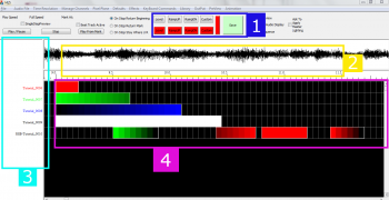
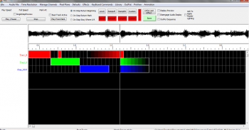
The HLS Sequencing Window has four basic components which are important when sequencing (See Figure 5-1).
1. The first component, highlighted in blue, is the toolbar for applying effects in a sequence.
- The top row of buttons are basic effects.
- The second row of colored buttons are the colors set for RGB channels.
2. The second component, highlighted in yellow, is the audio oscilloscope and the time bar, which shows where you are in the song.
3. The third component, highlighted in turquoise, is the listing of channels that are currently being viewed.
4. The fourth component, highlighted in purple, is the sequence grid, which contains the cells where effects are applied to channels.
Selection Mode in HLS
Applying effects to channels in HLS works differently than some other sequencing programs. When you click the left mouse button in the channel grid, the Selection Mode becomes active and will remain active until you click again or press the ESC key.
- TIP: Sometimes it may appear as if HLS is unresponsive or hung up. Most likely, you are in Selection Mode and HLS is waiting for a selection box to be completed. If things ever appear hung up or unresponsive, press ESC.
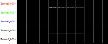
Basic Method to Create a Selection Box:
- Use the left mouse button and click in the left-most cell that the effect will be applied to.
- A dotted line will appear around the cell.
- Drag the mouse to the right (and down to apply to multiple channels).
- Click the left mouse button again when in the right-most cell that the effect will be applied to.
- All of the cells you have chosen will be surrounded by a dotted line. (See Figure 5-2).
- Note: If you are not happy with your selection, press ESC and draw the selection rectangle again.
Basic Effects
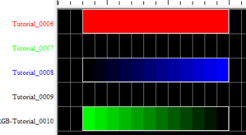
Level:
- Shortcut key: L
- Level effects are at the same intensity (default 100%) throughout the effect length.
- To add a Level effect, place a selection box around an area of cells.
- Press the L key or click the Level button on the menu bar.
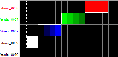
- See Figure 5-3, Channel Tutorial_0006.
Ramp Up:
- Shortcut key: U
- Ramp Up effects start at a low level intensity (default 0%) and move up to a higher level intensity (default 100%) throughout the effect length.
- To add a Ramp Up effect, place a selection box around an area of cells.
- Press the U key or click the Ramp Up button on the menu bar.
- See Figure 5-3, Channel Tutorial_0008.
Ramp Down:
- Shortcut key: D
- Ramp Down effects start at a high level intensity (default 100%) and move down to a lower level intensity (default 0%) throughout the effect length.
- To add a Ramp Down effect, place a selection box around an area of cells.
- Press the D key or click the Ramp Down button on the menu bar.
- See Figure 5-3, Channel Tutorial_0010.
Modifying Effects
Moving Effects:
- Moving an effect is to move it from one place in a sequence to another, such as moving it to start 1/2 second later than currently setup.
- Left-Click on the first cell of the effect to move.
- Move the mouse pointer to the new location.
- When satisfied with the change, left-click again.
Stretching and Shrinking Effects:
- Stretching an effect is to lengthen the time an effect will take place.
- Shrinking an effect is to shorten the time an effect will take place.
- Left-Click on the last cell of the effect to stretch or shrink.
- Move the mouse OUT from the starting cell to stretch or IN towards the starting cell to shrink.
- When satisfied with the change, left-click again.
Deleting Single Effects:
- Deleting an effect is removing the selected effect from the channel.
- Right-click on an effect and select Delete this Effect.
- Warning: No confirmation screen will appear.
Deleting an Area of Effects:
- Deleting an area of effects will remove all the effects inside a selection box.
- Use the left mouse button to click on the left most cell and drag right (and down, if applicable) to select the end of the area you wish to delete.
- Left-click again to finalize the selection box.
- Right-click and select Delete Selection.
- Warning: Always be sure you know what is contained in the Selection Box. Once it's gone, it's gone!
Copy/Paste Effects:
- This is copying and pasting of an effect from one area to another.
- Select the effect you wish to copy by CTRL + Left-Clicking the left-most cell to copy. (This lets HLS know that you are wanting to select cells rather than move the effect.)
- Move the mouse to the end of the effect to copy.
- Left-click to finalize the selection box.
- Right-Click and select Copy from Selection Box.
- Tip: Use the shortcuts CTRL+C to copy and CTRL+V to paste.
- Move the mouse to the desired location for the copied effect, and left-click to finalize the selection.
- Note: The selection box will retain the size and shape of the copied cells.
- Press CTRL+V or right-click and select Paste from Selection Box to paste the copied cells.
Modify Effect Attributes:
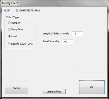
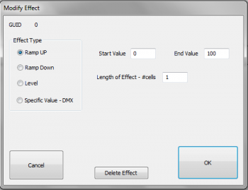
- Effects can be modified in length, type of effect, intensity, and deleted all from this window.
- Right-click an effect and select Modify This Effect. The Modify Effect window will appear (See Figure 5-4).
- Change the effect type using the radio buttons.
- If the effect is a ramp, you can adjust the beginning and ending intensities.
- If the effect is a level, you can adjust the overall intensity.
- You can assign specific DMX values to a channel, so values from 0-255 instead of percentages of 0-100.
- For all effects, you can adjust the number of cells.
- You can also delete the effect by clicking Delete.
Adding and Using Beat Tracks
Introduction
A Beat Track is a "channel" which is not actually assigned to any output. It's only purpose is to have markers in the sequence which have been set at points where a beat or some other repetitive musical component is found in a song. A beat track helps easily sequence movements between lighting channels so that the movements fall at appropriate musical points. An example would be an arch that moves from one end to another between two beat marks.
HLS supports creating beat tracks in a couple of ways. One way is to manually press a button or click a mouse while a song is playing to set the beat. Another way would be to apply a filter to the audio and then manually "turn on" the beat track at points identified through the filter.
Add Beat Track Channels

First, channels must be added so you can use them as beat tracks.
- Open the Channel Manager (Manage Channels -> Manage Raw Channels)
- Since we are going to look at three different ways to create a beat track, go ahead and Add 3 channels named "Beat".
- Keep the Universe as 0 since these channels will not be associated with real output.
- Use the color Selector to set colors for your beat tracks (see Figure 5-5).
- When done, select Save Changes.
Setting Display Group for Beat Track

- Next, assign all of the beat tracks into their own Display Group.
- Create a Display Group named "Beat" and add all three channels (See Figure 5-6).
- Set the "Beat" display group as the group to work with.
Beat Track From Clicks
Creating a Beat Track from Clicks is one of the easiest ways to create a Beat Track. Clicks must be quick and not everything will line up perfectly, but it can give reasonably good results.
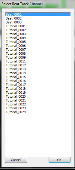
- Activate the Beat Track by clicking Manage Channels -> Select a Beat Track Channel.
- Select the Beat Track you want to use and click OK (See Figure 5-7).

- Check the box Beat Track Active to let HLS know that you are planning to record clicks for a beat track (see Figure 5-8).
- Press the Play / Pause button to play the song.
- Press the CTRL key or the Left Mouse button at each beat in the song.

- When the song is complete, there will be two grid cells filled in at every click received. Your beat track has been created. (See Figure 5-9)
Beat Track from Filters
This is a very powerful feature of HLS and one that can come in handy when setting up beat tracks. You get to this by clicking Audio File -> Apply Lo or Hi Pass Filter or Band Pass. The DSP Filtering window will open (See Figure 5-10).
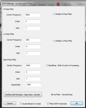
- Hi Pass Filter: This filter will filter the audio to only show the portions that are in higher frequencies, such as a female vocal or high (in pitch, not volume) notes.
- Wikipedia: High Pass Filter
- Lo Pass Filter: This filter will filter the audio to only show the portions that are in lower frequencies, such as bass drum and other low (in pitch, not volume) notes.
- Wikipedia: Low Pass Filter
- Band Pass filter: This filters on BOTH high and low frequencies. The Frequency value is the "desired" frequency. A band pass filter will filter OUT both the high and low frequencies that are further away from that frequency.
- Wikipedia: Band Pass Filter
Applying the Filter:


- Choose the filter you wish to use, enter the needed information, and click OK. You can also use the "Stay Here" option to apply the filter and continue working with the audio without closing the Filtering window. (See Figure 5-11a and 5-11b for an example of the audio before and after applying an 8 khz filter to attempt to isolate a cymbal sound.)

- Once the sound has been isolated, manually add effects where the sound is present. In the example, Beat Track 2 is being used to mark two cells with a Level effect at each cymbal sound (see Figure 5-12).
- Tip: To speed up this process, you may find that using the CLICK filter AFTER applying the DSP filter will allow you to click accurately with the sound you want isolated rather than manually drawing in the effects.
- Once finished with the filter, return the audio to normal by choosing Audio File -> Remove Filter.
Common Sound Frequencies:
- 200 Hz and below: The bass of the mix. The bottom end of the sound.
- 200 – 400 Hz: The body of the low end instruments.
- 400 Hz – 1 kHz: The low mid/mid area of the mix. The body of guitars and vocals reside here.
- 1 – 3 kHz: Snare drums and kicks start in this range and extend almost to 4 kHz.
- 4 – 8 kHz: High-mids, the top end of most drums, guitars, and organs. Also the body of cymbals is in this range, bottoming out in 3 kHz range.
- 8 – 10 kHz: Cymbals mostly live here. You’ll also find the top end of vocals here.
- Summarized from: abovegroundmagazine.com
Visual chart of instruments and frequency ranges: frequency chart
Video
- Watch this video uploaded by Joe Hinkle. (Note: This video link starts at the 3:22 mark, where discussion of the DSP filtering begins.)
Cleaning up a Beat Track
Whether manually clicking or using filters, some of the beat track marks may be slightly off from where you want them. You can slow a song down and use the oscillioscope to "cleanup" the marks.
- To move a mark left or right, Click on the FIRST grid-square, release the mouse button, and then move it using the mouse and dragging.
- When the timing mark is placed where you want it, click on it again (or press escape) to exit selection mode.
Setting Beat Track as a Sticky Channel
You can set a single beat track or multiple tracks (up to three) to remain "stuck" to the top of the sequencing window by setting Sticky Channels.
Setting Defaults for Effects
Choose the Defaults tab on top of HLS and select the item you would like to set defaults for. For this example, Ramp Up was selected. The screen shown in Figure 5-13 will appear. You can change any values you would like and they will be saved as the new default values for the current sequence.
Creating Chase Effects
A chase effect is an effect that spans multiple channels with a lighting effect that moves through those channels over a period of time. When it is set to lights, it creates an appearance of a "chase" through lighting channels. Chases can be created manually in HLS, or, through an Action menu to chase a group (the easy way).
Manual Chase
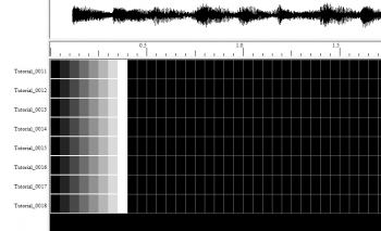
- For illustration, we will be adding a chase to eight channels. First, add the effect you want to chase to each of the eight channels. This can be level, ramp up, ramp down, or any other effect for a single channel. (See Figure 5-14 for an example where Ramp Up was chosen to run over 8 cells in each channel.)
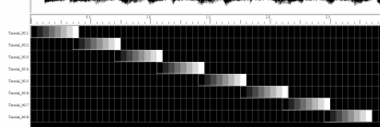
- Next, slide each channel effect to create the chase. This is done by clicking on the left-most cell on channel 2 first, then moving the mouse to the right. All channels in the effect will slide to the right. The same procedure is to be used for the rest of the channels. The results are shown in Figure 5-15.
Chase (The Easy Way)
- For illustration, we will be adding a chase to eight channels. First, add the effect you want to chase to each of the eight channels. This can be level, ramp up, ramp down, or any other effect for a single channel. (Look up to Figure 5-14 for an example where Ramp Up was chosen to run over 8 cells in each channel.)
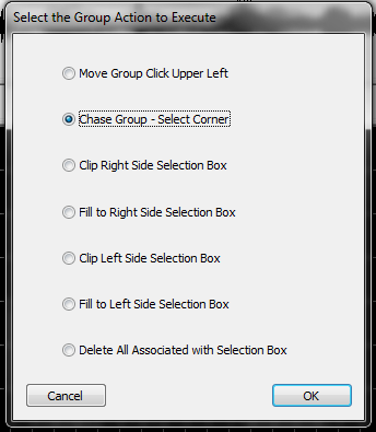
- Next, select the cells in all eight channels that you want to chase. (Remember to CTRL-Left click the left-most cell to let HLS know you want to select instead of move.)
- Once the selection-box is complete, Right-click the group of cells and select Perform Action on Selected Group.
- In the menu that opens, select Chase Group and click OK (see Figure 5-16).
- Click in one of the corners and move the mouse to pull the channels apart into a chase formation.
- When satisfied with the result, left-click again and hit ESC (Look up to Figure 5-15 to see end result).
- Tip: BOTH methods can create the SAME end result. However, the built in chase function is much faster.
Video: Chase Effects
Mirroring Effects
Mirroring is taking an effect or group of effects,and flipping them horizontally or vertically.
The following image demonstrates the sample channels which will be used to mirror.
Horizontal Mirror:
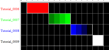
- Enter Selection mode and select the group of effects to mirror (See Figure 5-17).
- Note: Remember, to select effects, you must CTRL-left-click.
- Right-click on the group and press CTRL+H or select Flip Horizontal Selection Box (see Figure 5-18).
- Tip: If you create a selection box longer than the object to be flipped, HLS will flip and move it to the right-most cells.
Vertical Mirror:
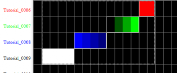
- Enter Selection mode and select the group of effects to mirror.
- Note: Remember, to select effects, you must CTRL-left-click.
- Right-click on the group and press CTRL+M or select Flip Vertical Selection Box (see Figure 5-19).
- Tip: If you create a selection box taller than the object to be flipped, HLS will flip and move it to the furthest away cells.
Fill Effects
Fill Effects "fill in" empty space with effect that "extends" the pre-existing effect. You can fill from specific directions to achieve the effect you want.
- Note: Fill Effects and Fill Channels are NOT the same thing. Fill Channels are used in conjunction with custom effects or pixel plane effects to fill in areas where the custom effect or pixel plane effect are off. Fill Effects are used in the same channel with your other effects to "fill in" the gaps.
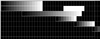
- Figure 5-20 shows various ramp ups applied to some channels. A selection box has been drawn around a number of the effects.
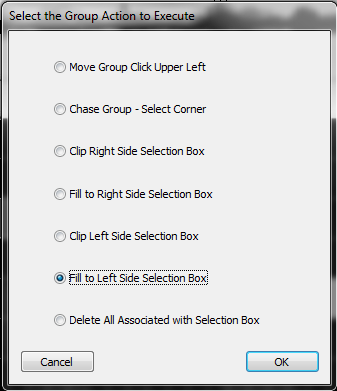
- Right-click inside the selection box and choose Perform action on selected group (See Figure 5-21).
- Click Fill to Left Side or Fill to Right Side, further explained below.

- Fill effects to the LEFT of the selection box will "stretch" all of the selected effects to the left until it reaches the left-most edge of the selection box. The empty spaces to the right will not be affected. See the result in figure 5-22.

- Fill effects to the RIGHT of the selection box will "stretch" all of the selected effects to the right until they reach the right-most edge of the selection box. The empty spaces to the left will not be affected. See the result in figure 5-23.
- Tip: Note that in the second row, the Fill to Right command picked up on the Right-most effect contained in the selection box to fill. If your selection box contains more than one effect in a row, it will always fill using the one closet to the "fill edge."
Submaster Lighting Channels
Template:Submaster Lighting Channels
Sequencing with RGB Channels
Introduction
RGB Channels are a special channel in HLS that consist of three output channels each. These would generally be used with RGB strings and display items, both "dumb" RGB and Pixels. However, they can also be used to reduce channel counts of "mega strings", or strings composed of three different color strands which are contained together in one.
RGB Channels in the Sequence Window
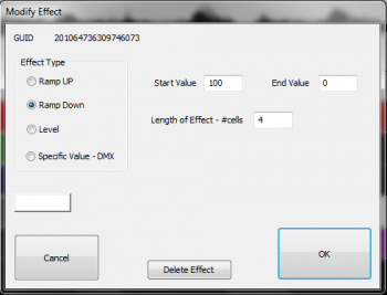
RGB Channels, when displayed in the sequence window, will place "RGB" in front of the HLS Channel name. This helps distinguish which HLS channels are RGB channels. When adding effects to RGB channels, HLS will use a white color by default. Once you have added white effects, you can right-click on the effects, choose Modify, and change the color by clicking the white-colored rectangle in the modify effect window (see Figure 5-26).
Managing Color when Adding Effects

Effects for RGB channels work the same as effects for regular channels. The difference is the addition of the color variable. While the previous sub-section mentioned a way you can sequence all in white and add color later, HLS has built in tools to allow you to apply basic effects in the color desired.
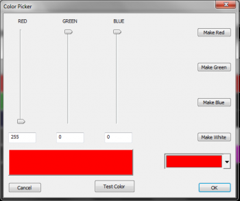
In the HLS window, there are colored effect buttons for Level, Ramp Up, and Ramp Down. See Figure 5-27. When you first open a sequence, these are red. The rectangle to the right of the buttons can be pressed which will open the Color Picker (See Figure 5-28).
- Click and open the Color Picker.
- Select a color for the effect you wish to add.
- Click OK to close the Color Picker and activate chosen color.
- Select desired grid cells to apply the effect, then click the colored effect button.
- Tip: Once you have clicked the colored effect button, you can now use the Keyboard Shortcuts to add additional effects to RGB channels. These effects will now be added with the picked color.
The HLS Toolbar
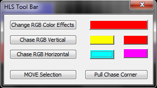
The HLS Toolbar is a floating toolbar that provides the use of several shortcuts when sequencing effects, including shortcuts that pertain to RGB channels. You can find out more about The HLS Toolbar and it's purposes.
- Change RGB Color Effects: Select RGB channel effects you wish to colorize. Click the large rectangle and select the desired color. Click the Change RGB Color Effects button and the selected effects will be changed to the desired color. Your effects and their values will remain the same.
- Chase RGB Vertical: Create a "color chase" on a vertical plane.
- Select multiple channels with pre-existing effects on a vertical plane.
- Click the first of the two color blocks in the row.
- Set beginning and ending colors for color wheel chase.
- Click Chase RGB Vertical button to chase through the colors on the wheel vertically through the selected channels.
- Chase RGB Horizontal: Create a "color chase" on a horizontal plane.
- Select multiple cells of a pre-existing effect on a horizontal plane.
- Click first of two color blocks in the row.
- Set beginning and ending colors for color wheel chase.
- Click Chase RGB Horizontal button to chase through the colors on the wheel horizontally through the selected grid cells.
Custom Effects
Introduction to Custom Effects
Custom Effects are a combination of multiple effects that can be applied to a sequence in a variety of ways. This creates a very custom yet clearly defined effect. This is one of the most powerful features of HLS. The first step is to create an effect template from defining an order of basic effects. Then, that template is applied to a selection box in a number of configurable ways to create the custom effect.
To create your first Custom Effect, click Effects -> Add a Custom Effect Group.
Building a Custom Effect Template
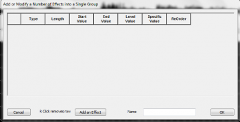
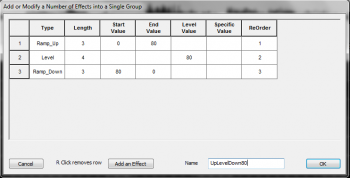
When you Add a Custom Effect Group, the Custom Effect window will open (see Figure 5-30).
- Click the Add an Effect button to add a row where you will enter your effect data.
- Column Definitions:
- Type: General type of effect (level, ramp up, ramp down, specific?)
- Length: the length of the effect in grid cells.
- Start Value: Intensity value at the start of the effect. (active for ramps only)
- End Value: Intensity value at the end of the effect. (active for ramps only)
- Level Value: Intensity value of a level effect. (active for level only)
- Specific Value: This sets a specific DMX value (0-255) rather than the normal behavior of percentage (0-100)
- Reorder: Used when reordering the effects that make up the custom effect.
- Continue adding effects until you have completed your custom effect.
- To remove an effect row, right-click on the left-most column (where the number appears).
- To Reorder effects, Change the numbers in the reorder column.
- Once you are satisfied with the components that make up your custom effect, type a name in the Name field and click OK (see Figure 5-31).
Placing a Custom Effect into a Sequence
Selecting Cells and the Custom Effect Template
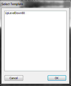
Now that you have built your custom effect, you can use it in a sequence.
- Select the grid cells and channels on which you wish to place the custom effect.
- Press the Custom button or C and a window will open for you to select the custom effect (see Figure 5-32).
- Select your effect and click OK. This will open the Execution of Effect window.
Executing the Custom Effect
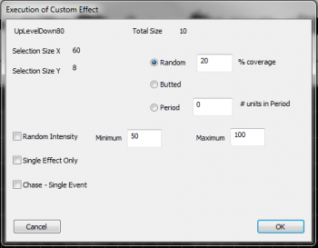
The Execution window (see Figure 5-33) is where you tell HLS very specifically how you want the custom effect applied. This is truly where the power and customization of HLS shines through.
The layout of the window contains basic information in the top left:
- The name of your custom effect template and it's size.
- Selection Size X/Y: This is the number of grid cells selected (X), and the number of channels (Y) that you will apply the effect to.
Modifying the pattern of how the effect is applied:
- Random Coverage: This will place the custom effect randomly throughout the selection box. The %Coverage lets HLS know what percentage of the cells contained in the selection box should be covered by the effect.
- Butted: This means the effects will be placed right next to each other. HLS will place your custom effect back-to-back in each selected channel all the way to the end of your selection.
- Period: This will apply your custom effect every defined period of cells. This period is the "wait time" before the next custom effect is applied. For example, a period of 4 would apply your custom effect, leave 4 grid cells blank, then reapply the effect, and so on.
Additional Modifiers:
- Random Intensity: This will apply your custom effect using a random intensity, from your custom low value to high value.
- Single Effect Only: This will apply your custom effect one time only, exactly as you defined it.
- Chase - Single Event: This will draw your custom effect one time, and chase it through the channels contained in your selection box.
RGB Channels and Custom Effects
- If you wish your custom effect to be a color other than white, use the color-specified custom button on the toolbar.
- Select the rectangle and choose the color you wish to use for the rgb channels. Click the color-coded custom button.
- Configure your Custom effect as described in the sections above.
- It will apply the custom effect in the color chosen.
Creating a Library of Group Effects
Introduction to the HLS Library
HLS contains a Library function, which allows the user to save group effects into a library file which can then be inserted into other places in the sequence or in other sequences. An example would be of saving an group of channel effects that create a wave of colors across a set of mini-trees. This wave could be reused in other places or sequences without having to be created from scratch. A library can contain multiple group effects. HLS can also contain multiple libraries, such as one for mini-trees, one for arches, etc.
- To view the Library, click Library -> Just View - See What's Available. When done, click Cancel to close the window.
Creating a New Library
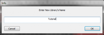
To begin, you must create a new library for HLS to store effects into. To do this, click Library -> Make New Library from the top menu bar. Type in a name for your new library and click OK (see Figure 5-34).
Saving Sequence Data to a Library
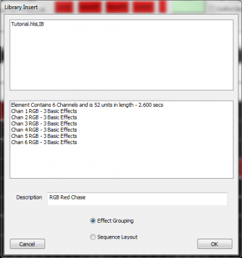
- Draw a selection box around the group of effects and channels that you would like to save to the Library.
- Click Library -> Add Effect Group to Library to assign the selected effects to a library (see Figure 5-35).
- Click on the name of the library you wish to save the group effect into. The bottom half of the window will show information about the effects being saved.
- Note: Make sure Effect Grouping is selected and not Sequence Layout.
- Name the group effect in the Description field and Click OK.
Inserting Saved Group Effects into a Sequence
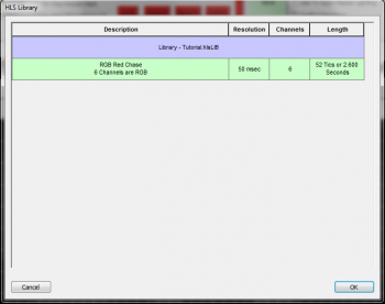
- It is recommended to save your sequence before adding an effect.
- To insert a saved group effect, click Library -> Insert into Sequence an Effect From Library.
- In the Library window that opens, select the saved effect you wish to insert. It will become highlighted in green (see Figure 5-36). Click OK to continue.
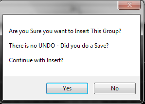
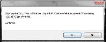
- After clicking OK, HLS will display a warning message (see Figure 5-37).
- To continue, click OK. Otherwise, cancel will abort the insertion of the group effect.
- HLS will display another window with instructions on how to tell HLS where you want the effect inserted (see Figure 5-38).
- Click Yes to continue.
- Left-click on the cell you wish to paste the group effect into. The effect will be pasted starting at that point.
- Once the effect has been inserted, you can then manipulate the individual effects as needed.
Removing a Library of Group Effects
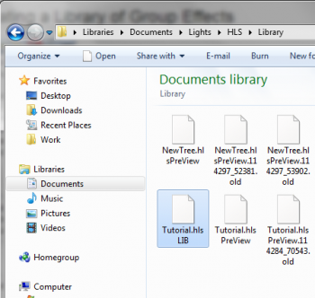
- Currently, you cannot delete Group Effects or whole Libraries from within HLS.
- A work-around to delete Libraries is to navigate using Windows Explorer to the folder that contains HLS.
- Navigate into the Library folder.
- Find the Library you wish to delete. It will have the .LIB extension and be named the same as the library inside HLS (see Figure 5-39).
- Select the file and delete it. HLS will now no longer contain that library or it's associated group effects.
Depreciated Library Functions
In the past, the Library function could be used to save Channel Layout for a sequence. This would allow you to reuse a sequence's channel setup, output setup, etc. with other sequences. This feature has been depreciated in favor of Using HLS Sequence Images.
Creating and Using PixelPlanes
Creating a PixelPlane (12Z)
What is a PixelPlane?
A PixelPlane is a grouping of pixels into a single channel that can be sequenced with complex effects on a macro level. By using PixelPlanes, HLS is able to completely remove the low-level complexity and allows the user to treat a large amount of channels as if they are one. Anyone sequencing with lots of pixels, using external programs like nutcracker, or looking for additional ways to "handle" pixels would benefit from this feature of HLS.
VIDEO: Joe describes a PixelPlane and creating a PixelPlane in his HLS 2013 Intro video
How to Create a PixelPlane
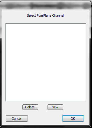
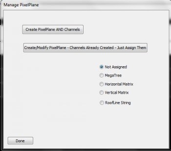
- First, open the PixelPlane Manager (Manage Channels -> Manage PixelPlane Channels).
- In the Select PixelPlane Channel window, press the NEW button to create a new PixelPlane (See Figure 6-1).
- The Manage PixelPlane window will open (See Figure 6-2). Click Create PixelPlane AND Channels.
- Note: In the past, PixelPlane Channels were first created in the regular Channel Manager. They are now created here. If you have already created channels (in the old way), or are importing from another file and want to convert channels to a pixel plane, select Create/Modify and select your channels manually and then save the changes.
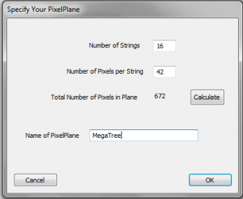
- The Specify Your PixelPlane window will open (See Figure 6-3).
- Enter the number of strings in your PixelPlane, the number of pixels per string, and then press the calculate button. (In the example used, 16 strings of 42 pixels were entered, which equals 16*42=672. Note that this is the number of PIXELS, not the number of CHANNELS.)
- Name your PixelPlane and click OK.
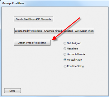
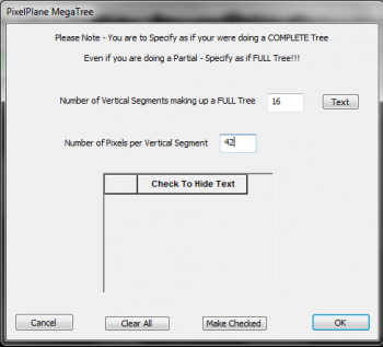
- Once you have created/named your pixelplane, a new button will appear to assign your pixels to a PixelPlane object (see Figure 6-4).
- If you select Vertical Matrix, a dialog box will open confirming you have assigned your pixels to a Vertical Matrix PixelPlane object.
- If you select MegaTree, a window will open for you to complete some information to help HLS understand your tree setup (see Figure 6-4b).
- Note: Currently, only "Mega Tree" and "Vertical Matrix" are supported.
- Press Done to close the window. Your PixelPlane has now been created.
Assigning Channels/Universe to PixelPlane
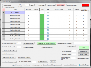
- To assign OUTPUT Universe and Channels to your PixelPlane object, go to the channel manager (Manage Channels -> Manage Raw Channels). (See Figure 6-5)
- When adding your PixelPlane, HLS will automatically create a Folder and place all of the related pixels into that folder. To open or collapse the folder contents, simply click on the folder name.
- Note: HLS PixelPlanes will already have an assigned "color," which is Green. This is just a representation color for PixelPlanes, and does not reflect an actual output color.
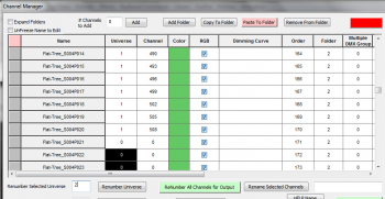
- By default, HLS will not assign DMX universes or output channels to your PixelPlane.
- FIRST, ensure your pixels are in the correct order.
- Highlight the first 170 HLS PixelPlane channels of your object and assign the DMX Universe Number by entering the number and selecting Renumber Selected Universe.
- Tip: Remember that Pixels contain 3 physical channels in each (R,G,B). A DMX universe can contain 512 channels. No single pixel can be split across a universe (unless using Multiple DMX), so only 510 can be used in a single universe. 510/3 = 170. Therefore, after every 170 pixels, you must use a new universe number.
- When done with Universe assignment, click Renumber Channels for Output to complete the channel assignment process.
- In the example of Figure 6-6, the first 170 HLS channels have been assigned to DMX Universe 1. For demonstration purposes, the Renumber all channels for output button was pressed, which then assigned that DMX Universe to physical channels. The next 170 pixels are now highlighted and ready to be assigned to DMX Universe 2.
Displaying a PixelPlane in the Sequencer Window
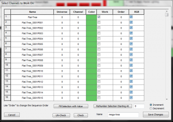

- Just like with any HLS channels, you must assign the PixelPlane to a Display Group to be able to work on it.
- Click Manage Channels -> Select Channels and Assign to Display Group. Click NEW to create a new group.
- Note: Do not add the actual pixel channels to the display group. ONLY add the one PixelPlane channel. (See Figure 6-7)
- Then, set the Display Group to the PixelPlane group to begin working on it (Manage Channels -> Select Display Group to Work on). It will show as a single channel. (See Figure 6-8)
- Note: Review Configuring Display Groups for more detailed instructions.
Sequencing Effects on a PixelPlane
Like any RGB channel, PixelPlane channels can have effects placed on them. You can do basic effects, such as Level, Ramp Up, and Ramp down. you can also do custom effects to the entire PixelPlane. These effects will globally change the entire pixel object.
As an example, you could add a ramp UP effect to a PixelPlane MegaTree. This would cause the entire tree to fade up from 0-100.
However, simple effects and even custom effects on an entire pixel object cannot fully utilize the power that can come with using the built-in PixelPlane Editor, which can generate a customizable library of effects. HLS also supports dropping in effects from third party applications, such as effects built with Nutcracker.
The PixelPlane Editor: Creating Effects (12Z)
Introduction
The PixelPlane Editor has a number of effects that can be created for various PixelPlane Objects. This page contains all of the possible effects and explanations of how to use them.
For explanation purposes, the effects are categorized in four groups:
- Whole Object Effects: Generate effects that light the entire (or almost entire) PixelPlane Object.
- Particle Effects: Effects composed of drawn particles which can be manipulated on the PixelPlane Object.
- Text Effects: Scrolling text on the PixelPlane Object.
- Image Effects: Generate images displayed on the PixelPlane Object.
Some of the effects are not usable for every PixelPlane Object. Each effect contains a listing of the Objects that it can be applied to.
Whole Object Effects
Bars (Horizontal)
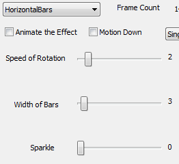
A Horizontal Bar effect creates horizontal bars that slide up or down the PixelPlane Object.
- Use With: MegaTree, Vertical Matrix.
Options to Customize a Horizontal Bar Effect:
- Motion Down: Move bars down instead of up.
- Speed of Rotation: How fast should the bars move up/down (lower numbers mean faster).
- Width of Bars: How wide the bars should be. This will also determine the number of bars that appear on the object.
- Sparkle: Add random sparkling pixels to the effect.
Bars (Vertical)
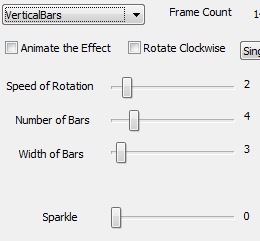
A Vertical Bar effect creates vertical bars that move across or around the PixelPlane Object.
- Use With: MegaTree, Vertical Matrix.
Options to Customize a Vertical Bar Effect:
- Rotate Clockwise: change rotation direction.
- Speed of Rotation: How fast should the bars move (lower numbers mean faster).
- Number of Bars: The number of bars to move vertically. Each additional bar will add a new color (max 6). Additional bars after that will repeat the color additions.
- Width of Bars: How wide the bars should be.
- Sparkle: Add random sparkling pixels to the effect.
Diagonal
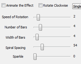
A Diagonal effect creates diagonal stripes that move across the PixelPlane Object.
- Use With: Vertical Matrix.
The Options to customize the Diagonal Effect:
- Rotate Clockwise: change rotation direction.
- Speed of Rotation: How fast should the Diagonal lines slide.
- Number of Bars: The number of bars on the diagonal. Each additional bar will add a new color (max 6). Additional bars after that will repeat the color additions.
- Width of Bars: How wide the bars should be.
- Diagonal: Angle of diagonal lines.
- Sparkle: Add random sparkling pixels to the effect.
Particle Effects
Fireworks
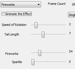
A Firework effect creates fireworks that streak down the PixelPlane Object. These are exactly the same as meteors, except when sparkle is applied. When it is applied, it will randomly "explode" the firework.
- Use With: MegaTree, Vertical Matrix.
Options to Customize a Firework Effect:
- Speed of Rotation: How fast should fireworks fall (lower numbers mean faster).
- Tail Length: Length of the tail of the firework.
- Fireworks: Firework density.
- Sparkle: Add random sparkling to the head of the firework. Unlike Meteor, Fireworks sparkles "explode" the head of the meteor.
Meteors
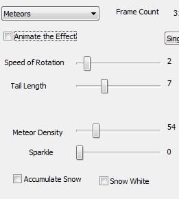
A Meteors effect creates random meteors that streak down the PixelPlane Object.
- Use With: MegaTree, Vertical Matrix.
Options to Customize a Meteor Effect:
- Speed of Rotation: How fast should the meteors fall (lower numbers mean faster).
- Tail Length: Length of the tail on the meteor.
- Meteor Density: How dense the "meteor field" should be.
- Sparkle: Add random sparkling pixels to the head of the meteor. Only the head will sparkle.
Snow
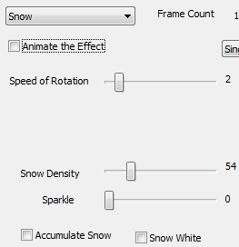
A Snow effect creates random snowing of randomly colored pixels on the PixelPlane Object.
- Use With: MegaTree, Vertical Matrix.
Options to Customize a Snow Effect:
- Speed of Rotation: How fast should the snow fall (lower numbers mean faster).
- Snow Density: How dense the snowfall should be.
- Sparkle: Effects how many snowflakes are white. To have all white snow, turn it up very high.
- Accumulate Snow: As snow falls, have it accumulate at the bottom of the tree.
- Snow White: Sets all accumulated snow as white, no matter what color it was when falling.
Text Effects
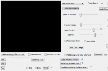
A Horizontal or Vertical text effect displays text that moves across the PixelPlane Object either horizontally or vertically.
- Use With: MegaTree, Vertical Matrix.
Options to Customize a Horizontal or Vertical Text Effect:
- Click Line 1 to enter text to display.
- Click Line 2 if you wish to enter a second line of text.
- Click Font to assign a font and size to the text display.
- Special note on Text with a MegaTree: Strings are oriented with string 1 in the 9 o'clock position. The numbering goes in a COUNTER-clockwise direction. Therefore, the FRONT of the tree will start at the 9 o'clock position and end at the 3 o'clock position. So, you want the "injection position" to be the END of the FRONT of the tree, and HIDE the back strings. Therefore, you will inject at your 3 o'clock position. So, for a 32 string tree, inject at string 16 and high 17-32. This will start text at the right end of the tree and run it "clockwise" towards the 9 o'clock position, String 1.
- Special note on Text with a Vertical Matrix: Strings are oriented with string 1 in the left-most position. So, you most likely want the "injection position" to be at the right-most string position, so that the text will start at the right of the matrix and run to the left across the matrix.
- Inject at String Position: This sets the first string for the text to begin drawing on.
- Pixel Gap between lines: This sets the amount of "dead pixels" between the two lines of text.
- Number Pixels Wait to Begin Again: Amount of "dead pixels" to scroll before the text appears again.
- Speed of rotation: How fast the text will move on the PixelPlane Object.
- Injection Height: This sets the height of where the text will display.
- Snow Density: This controls the amount of snow to appear with your text. (Must Check "Add Snow to Text")
- Sparkle: This adds a sparkle effect to the text.
- Add background color 6 to text: This will add the 6th color as background behind the text. The intensity field controls how bright that color is displayed.
- Note: You must click the Generate Text button before it will display in the animation window. Any changes made to text REQUIRE the generate text button to be pressed again.
Hide Text Strings:
- This allows you to turn off certain strings in a PixelPlane Object, such as the back of a MegaTree for text generation.
- Click the button and then check which channels are on the back of the tree. That will keep the text only showing on the front strings.
Image Effects
Animated GIFs
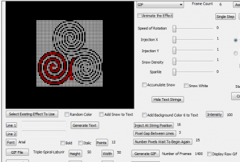
A GIF effect generates an animated GIF file that is displayed on the PixelPlane Object.
- Use With: MegaTree, Vertical Matrix.
Options to Customize a GIF Effect:
- Speed of Rotation: How fast the GIF should move between frames.
- Injection X, Y: Coordinates of where you want the image to be generated (Top-left would be 1,1).
- Sparkle: Add random sparkling to the GIF.
Selecting the GIF:
- Click the GIF File button and open your desired GIF file.
- Click the Height and Width buttons to let HLS know the dimensions to use when drawing the file on the PixelPlane Object.
- Click the Generate GIF button to complete setting up the file. Any changes to the file will require pressing the Generate GIF button again.
- HLS will output the number of animation frames included in the GIF file.
- Display Raw GIF will display the actual animated GIF file rather than the generated animation as it will appear in your PixelPlane Object.
Bitmap (Horizontal/Vertical)
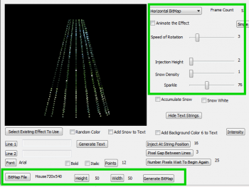
A Horizontal or Vertical Bitmap effect generates a bitmap file that scrolls across the PixelPlane Object horizontally or vertically.
- Use With: MegaTree, Vertical Matrix.
Options to Customize a Bitmap Effect:
- Speed of Rotation: How fast the bitmap should rotate horizontally or slide vertically.
- Injection Height: What height (in pixels) to start the bitmap.
- Sparkle: Add random sparkling to the bitmap.
Selecting the Bitmap:
- Click the Bitmap File button and open your desired bitmap file.
- Click the Height and Width buttons to let HLS know the dimensions to use when drawing the file on the PixelPlane Object.
- Click the Generate Bitmap button to complete setting up the file. Any changes to the file will require pressing the Generate Bitmap button again.
Using Nutcracker with a PixelPlane (In Process)
Introduction
Nutcracker is a pixel effect building system developed by Sean Meighan which is cross-platform with a number of sequencers, including HLS. In February 2013, Nutcracker 3.0 was released, which moved from a web-based application to a software-based version in conjunction with xLights. The use of nutcracker is beyond the scope of this document, but you can read more at the following links:
- Download Nutcracker, view tutorials, etc.
- DIYC Wiki Documentation on Nutcracker
- DIYC Subforum on Nutcracker
Nutcracker Setup for HLS
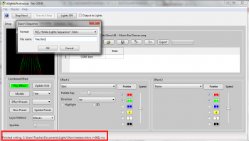
- When you configure Nutcracker, you should consider setting up the Pixel objects with the same configuration as your physical objects (ie, pixel count, strands, etc). HLS will utilize Nutcracker effects built for objects with different characteristics, but you will get more desired results from matching up configurations.
- Nutcracker exports to hlsnc files. Basically, once you have created your effect, click Export in nutcracker, choose HLS, name your effect, and click OK.
- Tip: Notice where Nutcracker is saving the export file by looking at the bottom of the window (see Figure 6-28 red highlight).
- This folder is set by clicking File -> Select Show Folder in Nutcracker/xLights.
Dropping a Nutcracker Effect Onto a PixelPlane
- Set the active display group to the one containing the PixelPlane you wish to drop the Nutcracker effect onto.
- Right click on the cell you wish to start the external effect, then select Add External PixelPlane Effect.
- A file dialog box will open. Navigate to the file exported by Nutcracker, select it, and click Open.
- The effect will be inserted into your sequence with the length that was created in the Nutcracker program.
- Note: If there are any previously created effects that occur before the nutcracker insert would end, HLS will stop the nutcracker effect early and butt it up to the next effect.
Using Start/Stop Markers for Adding Nutcracker Effects

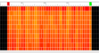
- This method is used to add nutcracker effects to pixels or RGB channels that may not be in a formalized PixelPlane object.
- First, set the display group to be the channels you wish to add the effect to.
- Set start and end marks, which tell HLS how many cells to fill with the effect (see Figure 6-29).
- Right-click to set the start mark (red), and CTRL-Right-Click to set the end mark (green).
- Click Pixel Plane -> Drop External Pixel Plane Effect Onto RGB Channels.
- HLS will give a couple prompts about making sure your settings are correct. Then, select your Nutcracker export file and click Open.
- You will be prompted to make sure Start and Stop marks are set properly. Since you have already done this, click Yes.
- The effect will now be dropped onto the active channels within the start and stop marks (see Figure 6-30).
Adjusting the Size of a Nutcracker Effect
- Use good planning when creating your effects in nutcracker so that they are as long as you may need. It is easy to shorten the effect, but not lengthen it (without adjusting speed).
- Make your pixelplane channel with the nutcracker effect active.
- Just like any other effect, click the last cell in the effect and moving it in or out to shorten/lengthen.
Note: Once you reach the length of the effect data, it will no longer stretch.
- Just like any other effect, you can move its starting point by clicking the first cell and moving it.
Adjusting Speed of a Nutcracker Effect
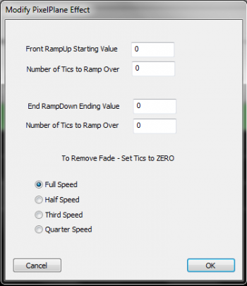
- Sometimes, the nutcracker effect may move at a speed that may be too fast or slow for your sequence.
- To adjust the speed, right-click on the effect and select Modify this Effect (see Figure 6-31).
- You can add ramp values if you wish to start from one intensity level, bring the effect up, then bring the effect down.
- Ex.: To ramp up from 10% to 100% over a 5 cell time, set ramp up to 10, and tics to 5.
- Speed can be adjusted by selecting one of the speed choices.
- Tip: A slower speed means that the effect can now be lengthened to last a longer period of time.
- Once done, click OK.
Fill Channels (12Z)
Fill Channels are designed to work with custom effects, such as the Pixel Plane. A Fill channel is a channel that "fills in" the background of pixel plane effects. This allows the opportunity to add background fill without messing up the complex effects that you have created. When a Fill Channel is activated, it will ONLY turn on when your PixelPlane effect is displaying. And it will ONLY light the OFF pixels.
VIDEO: Joe describes Fill Channels in his 2013 Intro video
Setting up a Fill Channel:
- Open the Fill Channel Manager: Manage Channels -> Manage Fill Channels
- Click New and assign a channel to function as a fill channel.
- Add the fill channel and your PixelPlane channel to the same display group.
- Add background effects to the fill channel. These can be different colors, fades, etc.
Engaging a Fill Channel:
- A Fill Channel must be engaged for it to show up.
- In the main window, click Ask to Apply Master Lighting.
- When you hit PLAY, the Master Lighting window will open. You don't need to check anything. Just click OK.
- Your fill channel will now be active and will display when PixelPlane effects are playing.
Video:
PixelPlane Transitions Using Lighting Channels (12Z)
Transitions between PixelPlane effects by fading out one effect and fading in another, will add a clean and professional look to your musical sequence. HLS can apply fades to complex sequence components by using Submaster Lighting Channels.

- Follow the steps in Submaster Lighting Channels to setup a new Submaster Lighting Channel and to Associate it with your PixelPlane channels.
- Note: You will have to highlight and check all of the pixelplane object channels directly. The PixelPlane group channel will not appear in the lighting manager channel selection window.
- Add your PixelPlane object and the lighting channel to the same Display Group.
- Add a Ramp Up at the beginning of the effect and a Ramp Down at the end of the effect.
- Figure 6-32 shows two PixelPlane effects. There is a Ramp Up into the first effect, a Ramp Down at the end, and a Ramp Up to the next effect.
- Ensure the lighting channel is active to turn the ramps on.
- Note: Submaster Lighting Channels will ONLY affect grid cells where the lighting channel effect value is greater than zero. In other words, if there is no effect on the lighting channel, the associated channels will run their effects normally. They will only be affected by the lighting channel in those cells where you have applied effects to the lighting channel. (As in the figure above, where there is no effect on the lighting channel between ramps, the effects run normally.
Drawing a PixelPlane in the Display Preview (12Z)
Note: Be sure to read the section on Creating a Display Preview to get an understanding of how Display Previews work and how to set it up. While this will cover the steps for a PixelPlane, it is assumed that you have an understanding of the basics.
Assigning Your PixelPlane Object to a Preview Group:
- Open the Channel Manager (Manage Channels -> Manage Raw Channels).
- Open your PixelPlane object by clicking its folder.
- Highlight all of the PixelPlane channels.
- In the Preview Group/Number bulk renaming field, enter your starting group, followed by a comma, followed by the number of pixels in each string.
- Example: A MegaTree with 16 strands of 50 pixels each would be entered as 1,50. This would number each string to its own display group.
- Click Done with Changes.
Drawing the PixelPlane Object:
- Open your Preview (Preview -> Edit New Preview). Then, select Pick Preview and select your preview file and click Ok.
- In the Preview Toolbar, click the button that represents your PixelPlane object.
- Draw the object in the window and press Spacebar.
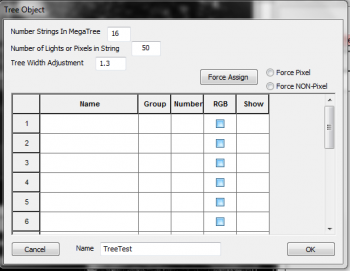
- Figure 6-33 will appear.
- Enter the number of Strings in your object.
- Enter the number of lights or pixels in each string.
- Enter a name for the object.
- Click the create button.
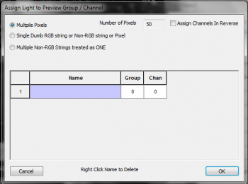
- Now you must assign your pixel strings to the appropriate preview strings.
- Click in the name field of string 1.
- Figure 6-34 will appear.
- Select Multiple Pixels
- The Number of Pixels field will automatically be filled.
- Click "Assign Channels in Reverse" IF your strings run in reverse.
- Click in the blue name field.
- In the window that opens, select the first string, first pixel.
- Click OK to close the Assign Light window.
- In the Object window, Select Force Pixel and then click Force Assign.
- Click YES to the dialog box.
- This will load all additional pixels and strings.
- To verify correct loading, you can now left-click in the show box to see the string light up in the visualizer window.
- Click SAVE to save the preview.
- Close the preview.
- Note: Follow directions in Creating a Display Preview to set a display preview as active and view your sequence while running it.
Facial Animation
Facial Animation
Content needed
Sequence Playback
Sequence Playback (12Z)
Sequences are played using the toolbar at the top of the screen (See Figure 8-1) or using shortcut keys.
Buttons/Keys:
- Play/Pause (F1 or 1)
- Pause (F3 or 2 or ,)
- Stop (F5 or 3 or .)
- Play from Mark (F7 or 4 or /)
Stop Functions:
- On Stop Return Beginning: When the STOP button or key is pressed, the song will return to the beginning.
- On Stop Return Mark: When the STOP button or key is pressed, the song will return to the Red starting mark.
- On Stop Stay Where U R: When the STOP button or key is pressed, the song will stay at the current location.
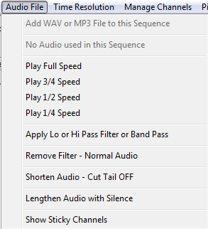
Playback Speed:
The Speed Control handles playback speed of the audio file. Being able to adjust the playback of the audio assists in proper timing placement in faster songs or just getting timings very precise. To activate, click the speed desired from the Audio File menu and then click the play button (See Figure 8-2).

Start/Stop Marks:
- It is possible to choose a different start point in the song and have the play button begin at that point.
- To select a new start point for play, right click your mouse on the timeline where you would like to start playing.
- A Red mark will appear in the timeline (see Figure 8-3).
- Click the Play From Mark button to begin play at that point.
- If desired, select On Stop Return Mark to return to the mark when the stop button is pressed.

- A Stop Mark can also be set in the song, which will cause the song to stop playing once it reaches the stop mark.
- To select a new Stop Mark, CTRL + Right Click your mouse on the timeline where you would like to stop playing.
Sequence Output
Hardware Configuration (Being Revised)
Introduction
To output your sequence data to your light controllers, there are specific components that must be defined in HLS output settings:
- Physical Hardware Settings
- This is where you setup COM ports or Ethernet/Wireless connections to get the sequence information "out" to your controllers.
- Universe Assignment
- HLS then has to know where the sequence data for a universe of channels should go (either a COM port or network connection previously setup).
- Output Protocol
- Finally, HLS has to know what "language" (output protocol) your controller speaks (Renard, DMX, sACN(DMX over Ethernet), or straight RS485)
Physical Hardware Settings
Setting Up Com Ports
The first thing you will need to do is determine what port numbers are assigned to your com device(s). For Windows, you can follow this guide.
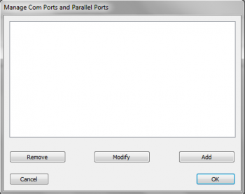
- After determining port numbers, click Output -> Setup COM Ports in the HLS main menu (see Figure 9-3).
- To add a new COM port, click Add.
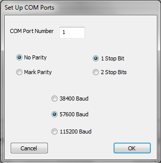
- In the window that opens, enter the appropriate COM number, then click OK (see Figure 9-4).
- Note: Other settings are correct by default and most likely need not be adjusted.
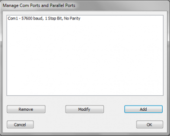
- Once your port(s) have been added, they will appear in the COM Port Manager (see Figure9-5).
- If you need to modify or remove a port, select it and click the appropriate button.
- Once done adding and modifying COM ports, click OK.
Setting up a Network
- Network card determination: Plug cable, remove cable.
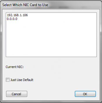
- To setup the use of a network card, click Output -> Select Specific NIC Card (see Figure 9-6).
- Select the appropriate IP address for the network card you wish to use.
- Note:' This can be a physical connection or a wireless connection.
- If you check Just Use Default, HLS will send out network data on whichever network connection you have set to default and active at that time.
- Once you have selected your network connection, click OK.
Universe Assignment
Once the physical hardware connections have been defined, HLS needs to know where to send each universe of channel data.
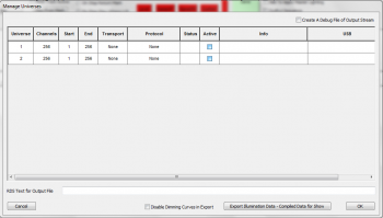
- Click Output -> select Output Method and Compile for Show.
- Each of your created universes will appear. (See Figure 9-7.)
- Three things must be configured for each Universe:
- Transport: What port to use for output (COM or Ethernet).
- Protocol: What "language" to speak to the controllers (Renard, DMX, sACN DMX).
- Active: Checking this box makes the universe Active for output.
Transport
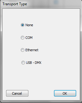
- Click the Transport column to choose the method of output.
- These were previously setup in the Physical Hardware Settings.
- Select your type of transport for the universe selected, then click OK.
Protocol
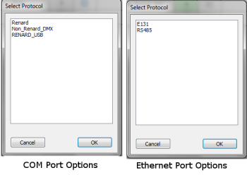
- Choose the protocol you wish to use (see Figure 9-9).
- For COM ports, you can choose Renard, DMX, or Renard_USB.
- For Ethernet ports, you can choose E1.31 or RS485.
Active

- Once you have assigned the protocol and transport, Status will be green or read 1 if everything is setup properly (see Figure 9-10).
- Check active to make that universe active for output.
- When finished assigning universes to outputs, click OK.
Output Sequence

- In manage Universes, verify the Active checkbox is checked.
- In the main sequence window, click Output Sequence next to the save button (see figure).
- Click Play to run the sequence and output lights to the controller(s).
Hardware Tests
Testing hardware.
Working with Playlists
Playlists are a list of exported illumination data from sequences that you can place in a play order. You can then add playlists into a schedule.
Exporting Illumination Data

- Before a song can be added to a playlist, the illumination data must be exported.
- Click Output -> Select Output Method and Compile for Show.
- Verify all universes are assigned to hardware appropriately.
- In the bottom right, click the Export Illumination Data button (see Figure 9-12).
- Check the Disable Dimming Curves box if you want to ignore any applied dimming curves.
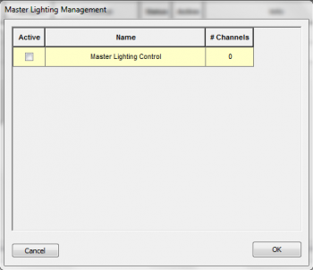
- A window will open listing any master/submaster lighting channels (see Figure 9-13).
- If you wish these lighting channels to be applied to the export, click the Active box.
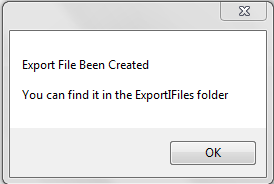
- Once all options have been completed, the export completion confirmation will show (see Figure 9-14).
- Repeat these steps for ALL sequences you wish to use in your playlist.
Adding Exported Songs to a Playlist
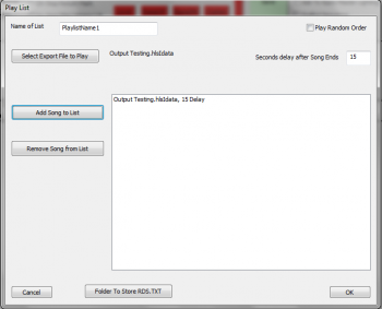
- Close down and reopen HLS without opening a sequence.
- To create your playlist, click Output -> Create a Playlist.
- The Playlist Window will open (see Figure 9-15).
- Type in a name for your new playlist.
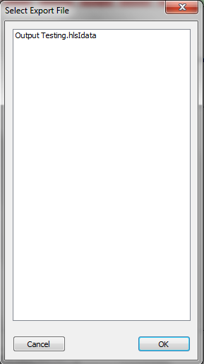
- Click Select Export File to Play.
- This will list all of the sequences with exported illumination data (see Figure 9-16).
- Select the desired file and click ok.
- The selected file will now be listed next to the Export button (see Figure 9-15).
- Adjust the Seconds Delay after Song Ends field to the desired time delay.
- Click Add Song to List to add the song to your playlist with the specified delay.
- Continue doing this until all songs are added to your playlist.
- If you wish the songs to play randomly, click the Random checkbox.
- When complete, click OK.
Modifying an Existing Playlist
- To modify an existing playlist, click Output -> Modify Existing Playlist.
- Select the playlist you wish to modify and click OK.
- The playlist window will open, allowing you to make changes.
Playing a Selected Playlist
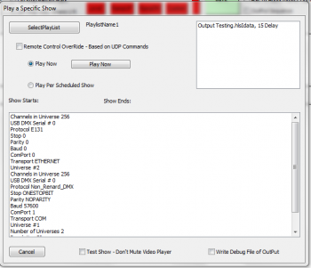
- To play a selected playlist, click Output -> Play Specific Playlist (see Figure 9-17).
- Note: You cannot have a sequence open to perform this action.
- Click Select Playlist and select the desired playlist.
- Select Play Now and click the Play Now button.
Creating and Running a Schedule
Introduction
Schedules are used to automatically run specific playlists at desired times and days during a week.
To Create a Show Schedule:
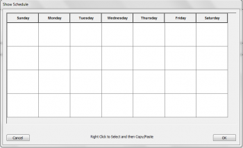
- Click Output -> Create/Modify Show Schedule (see Figure 9-18).
- Left-click on a blank space for the day you wish to schedule.
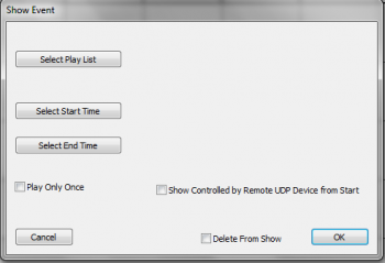
- The Show Event window will open (see Figure 9-19).
- Select Playlist and choose desired playlist from list and click ok.
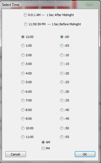
- Click Select Start/End Time (see Figure 9-20).
- Select any additional options, then click ok.
- When your schedule is complete, click OK.
To Copy/Paste:
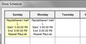
- To copy a configured show from one day to another, right click on the cell you wish to copy.
- The selected cell will turn "yellow".
- Right-click in the new cell that you want to copy the show into.
- The copied show will now be in the new cell.
To Delete/Modify:
- Left-click on the cell with the schedule you wish to delete or modify.
- This opens the Show Event window (see Figure 9-19). From here, you can make any changes you need.
- To Delete from that selected cell, check the Delete from Show button and click ok.
To Run a Scheduled Show:
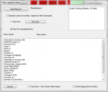
- Click Output -> Play Show Schedule.
- Select the playlist you wish to play.
- Ensure Play per Scheduled Show radio button is selected.
Advanced Hardware Configuration
Trigger Events
Content needed
RDS Output
RDS-enabled radios are found in many of today's vehicles. By using an FM transmitter with RDS capability, text information such as artist and song title can be broadcast along with the audio. HLS can work with any RDS software that looks for and reads in changes to a text file.

Setting the information in the sequence to be sent:
- Select Output -> Select Output Method and Compile for Show
- Figure 10.2-1 will appear.
- In the field "RDS Text for Output File", enter the text you would like displayed to RDS-enabled radios and click OK.
- Note: You will need to set this up for each sequence.
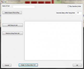
Setting the location of the text file to be written to:
- If you have a sequence open, close down HLS and re-open.
- Select Output -> Create a Playlist
- Figure 10.2-2 will appear.
- At the bottom of the window, select Folder to Store RDS.TXT
- Navigate to the appropriate location of the text file, then follow the steps on Working with Playlists to create and save your playlist.
Setting up the text file:
- Depending on the transmitter used and the software that comes with it, you will need to follow steps to let the software know where to look to find your saved RDS.TXT file.
- Tip: This should be setup and tested (by typing text in to the file and saving it) to work out any kinks before adding HLS to the mix (to simplify trouble-shooting). Once you have verified the RDS system is working, delete any text in RDS.TXT and save.
Servo Motors
Content needed
Importing and Exporting Data and Sequences
Using HLS Sequence Images (12Z)
Introduction
HLS Sequence Images are a template of saved sequences that can be used when starting a new sequence. The HLS Image contains everything setup in a sequence other than sequence data. This means that if you save an image, you can create a new sequence with that image which will contain your channel setup, previews, display groups, etc. You can have different image files for different shows you may run, such as Christmas, Halloween, or 4th of July.
Saving an HLS Image
Before you can create a sequence based on an image, you must create the image from a pre-existing sequence.
- Open the sequence you wish to create an Image from.
- Click File -> Create Image Without Effect to create the Image.
- HLS will save your image and pop up a window saying Save Complete.
- Click OK and then close and re-open HLS.
- Note: HLS saves these files in the HLS/Library folder with a naming scheme of: SequenceName_Image_XXXXX.img. SequenceName is the name of the sequence saved from, and XXXXX is numbers based on when it was saved.
Applying an Image to a New Sequence
- Open HLS and click File -> Start NEW Sequence USING a SAVED Image.
- HLS will prompt you to verify you want to use a saved image. (Click yes). See Figure 11-1.
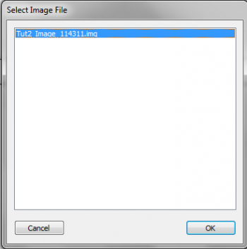
- HLS will then open a window with all previously saved Images for you to choose from. See Figure 11-2.
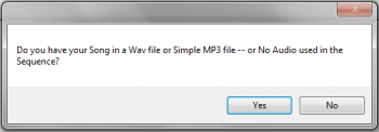
- Select the image you wish to use, and click OK.
- HLS will then ask if you want to use an audio file (YES for audio, NO for a sequence of no audio). See Figure 11-3.
- Continue to follow the steps presented in HLS Sequence Creation Wizard.
- Once your sequence has been created, HLS will save it. All of your previously created channels, display groups, previews, output settings, etc. will now be available in your new sequence.
Importing and Exporting CSV
Introduction
To aid in mass channel configuration and changes, HLS allows the user to export channel information to CSV (Comma Separated Values). This is a common text-based data export that can be imported in various programs, such as Excel. This exported data can then be viewed in another program, modified, and then imported back into HLS.
- Some potential uses for this feature include:
- Adjusting channel information
- Creating new channels
- Printing channel information
Exporting Data to CSV

- To export your channel data, open the channel manager (Manage Channels -> Manage Raw Channels).
- In the bottom-right of the window, click Export CSV File (see Figure 11-4).
- A window will open confirming that the export is complete (see Figure 11-5).
- The location of the exported file will be inside the HLS folder for the sequence you exported information from.
- Ex.: Channel info exported from a sequence named "Carol". Go into the HLS/Carol folder and the exported file will be named Carol Export.csv.
Working With Exported Data

- Note: For this example, Excel will be used, but any program that can manipulate CSV files will work.
- Open the exported file in Excel.
- The Channel information will be listed in column format with headings explaining what each column value is for (see Figure 11-6).
- Guid: This is a unique identifier given by HLS for that channel.
- Current Name: The current name of the channel.
- Universe: DMX Universe the channel is assigned to.
- Channel: Output channel assignment.
- RGB: Boolean value (0 or 1) for whether the channel is RGB.
- Prev Group: Preview Group assignment.
- Prev Number: Preview Group Number.
- New Name: This field is used by HLS when channels are being renamed.
- Make desired changes Excel. Know that HLS is unable to apply any error-correction for values you put in here since you are modifying it outside of HLS.
- If you add channels, you will not have a GUID. HLS will assign this on import.
Importing CSV Data Into HLS
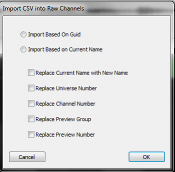
- Once changes have been made, save the CSV file.
- Go ahead and save your HLS sequence in case there is a problem with the import.
- Click Manage Channels -> Import CSV and Update Raw Channels.
- You will be prompted with a warning about saving your sequence. Click YES since you have already saved (Or click NO and save now).
- There are two ways to import the data (see Figure 11-7):
- Import based on GUID: Import and use the GUID when making changes to channel data.
- Import based on Current Name: Ignore the GUID field on import and copy any changes based on the Current Name field.
- Specific actions to take with the imported data:
- Replace Current Name with New Name: The "original" name of the channel will be replaced with the one you have entered into "new name".
- Replace Universe Number: Overwrite old DMX Universe number with data from CSV.
- Replace Channel Number: Overwrite old Output Channel number with data from CSV.
- Replace Preview Group: Overwrite old Preview Group number with data from CSV.
- Replace Preview Number: Overwrite old Preview Number with data from CSV.
- Once you have made the selections you need, click OK.
- Select your CSV file to import from and click open.
- HLS will now import the CSV data and will let you know how many matches were made, then save your sequence.
- Important: If you create NEW channels in CSV, you MUST FIRST create empty channels in the raw channel manager so HLS has a place to move that data into the sequence. If you do not do this, the data from those new channels will not be imported.
Importing a Sequence from Vixen (12Z)
- Follow the steps to create a sequence: HLS Sequence Creation Wizard
- Under the File menu, select Import a Vixen File. – You will be prompted to select the VIX file.
- Select the VIX file you would like to convert. Note that the HLS conversion will give the new HLS file the same name as your VIX file with different extensions. You may see a note about HLS making a slight timing adjustment to the VIX timing to make it more exact.
- Select OK, The conversion will take place and you will see a note showing that the channels have been converted. This may take some time.
- After the conversion you can choose the Manage Channels menu, select channels to create a group and work like you normally would with HLS.
==Importing a Sequence from LOR (12Z)
First, follow the steps to start a new sequence: HLS Sequence Creation Wizard
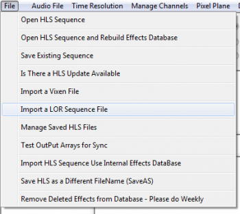
- Click File, Import a LOR Sequence File. Then navigate and select the appropriate LOR sequence for the audio just added to the HLS sequence. Also select the HLS sequence that was created. It will ask to overwrite. Select Yes. Once OK has been clicked, the conversion will begin (see Figure 11-10).
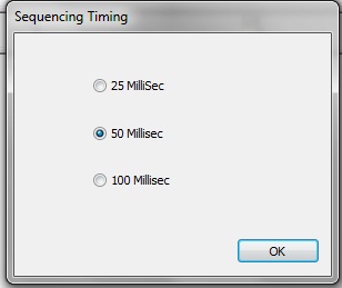
- Next will be a prompt to select a sequence timing interval (see Figure 11-11). It may be helpful to match the timing interval of the sequence being imported.
- A counter will show the status of the channel import process. Once complete, notification will be provided of the channels successfully converted into HLS. A prompt will appear to shutdown HLS to convert RGB channels (if any are present).
- Restart HLS (if needed) and open the sequence.
- Use channel manager to set up channels, configure groups, or add or delete channels.
Sharing HLS Sequences (12Z)
Files Needed for Sharing/Moving Sequences
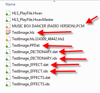
HLS creates a number of files in each sequence folder. Many of these are backups or potentially other files that are not needed when looking to share a sequence with another person. Another time you would do this is if you had a "work" computer that you did the sequence work on, but needed to move sequences to a "show" computer for the actual output.
Figure 11-12 indicates the files that should be included in a zip file when sharing the sequence.
- Note: The PCM file is the audio file in the sequence. This is an internal HLS file and cannot be played in a normal audio player.
Creating the Zip File
- Open Windows Explorer and navigate to your HLS Folder. Inside will be folders containing each of your sequences. Open the folder for the sequence you wish to share.
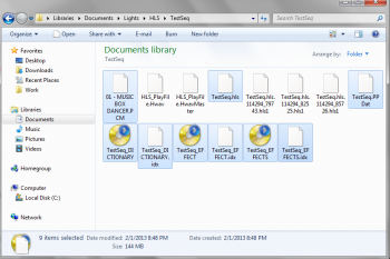
- Select the files that need to be included in the shared sequence. You can select multiple files by holding down the CTRL key and clicking desired files. (See Figure 11-13.)
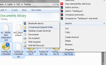
- Right-click on the selected files, select Send to -> Compressed (Zipped folder). See Figure 11-14.
- Your files will be compressed into a zip file. Name it and click enter. You can now share this file with others.
Sharing Library Effects (12Z)
Sharing Effects
Library effects can be shared between users of HLS. Someone may develop unique chases or other effects for certain display elements that you might find handy. You may also have created some useful library effects you would like to share with others. The idea is to help one another out rather than re-inventing the wheel.
Sharing Your Library Effects
- Open Windows Explorer and navigate into the HLS/Library folder.
- Each of your libraries will be saved as LIBRARYNAME.hlsLIB.
- Select the library files you wish to share, right-click on them, and choose Send to -> Compressed (zipped) folder.
- Name your Zip folder.
- Visit the DIYC forum thread for sharing Library files and post with your zipped file uploaded.
Using Someone Else's Library Effects
- Visit the DIYC forum thread for sharing Library files and download any attachments you wish to use.
- Extract the zip file into your HLS/Library folder.
- Open HLS and use the new libraries as you wish.
- Be sure to post in the forum thread thanking the member whose library you are using.
Copying and Pasting Channels from Another Sequence (12Z)
Introduction
By default, HLS is not designed to copy entire channels from one sequence to another sequence. You can copy and paste channels as you need within a single sequence, but, there is no pre-defined way to copy and paste to another sequence all-together.
Generally speaking, this would not be a common action, however, there are cases when it would be useful. For example, you might download an HLS sequence from the internet for a song you are currently sequencing. The sequence you downloaded may use arches in such a way that you want to use it as a base to sequence your own arches. Since you have already started on your own sequence of the song, the ideal would be to copy and paste the downloaded sequence's arch channels and paste them into your working sequence.
To copy and paste these channels, the Library can be used to carry over the channels to another sequence.
Creating a Library for Copying Channels
To keep your Library database clean, consider creating a new library that only contains copied sequence channels. Then, when you are done copying, you can simply remove that entire library since it will no longer serve a purpose. Review the Creating a Library page for instructions. Once you have your library created, go on to the next section.
Selecting Whole Channels for Sequence to Sequence Copying
- To select the entire channel, start at the left-most grid square of the song sequence.
- Left-click one time on the top-most channel you wish to copy to activate the selection box.
- Press and hold Page Down until you reach the end of the song sequence.
- Move the mouse to select all of the channels you want to copy/paste and left-click one time to fully select all channels.
Saving Whole Channels in the Library
- Click Library -> Add Effect Group to Library.
- Select the library you created for copying whole channels.
- Make sure Effect Grouping is selected.
- Type a name for your copied channels and click OK.
- Exit HLS
Pasting Copied Channels into the Desired Sequence
- Open the HLS sequence you wish to paste the copied whole channels into.
- Set the active display group to the channels that you will paste into.
- Click Library -> Insert into Sequence Effect from Library.
- Select the copied channels from the library.
- Click Yes, Yes to the prompts from HLS.
- Left-click in the left-most, top channel you wish to paste the channels into.
- Save your sequence.
Reference Guide
Restoring a Sequence from Backup (12Z)
By default, HLS will save a backup copy of your sequence each time that you save it. This allows the opportunity to back out of unwanted changes, problems, or any other issues. Therefore, it is best practice to save often, especially when making significant changes. This will then create a "trail" of files that will allow you to restore to an earlier time.
The backup files are located in your sequence folder. If you navigate to your sequence: HLS\Sequences\My Sequence, there are files in there with the extension hls1. These are the backup files saved each time you save your sequence.
To restore to an earlier version of a sequence:
- Open HLS
- Click the File menu, then select Manage HLS Files
- A dialog box will open alerting you to select the sequence to manage. Click OK.
- Navigate to the desired sequence, select it, then click OPEN.
- The picture shows a list of previously saved versions of your sequence file with the date and time of save. You can select one and delete it, or you can select one and make it the active file.
- Once clicking the Make Selected Backup Active HLS File, you will be asked to confirm. Say YES.
- You will then be prompted that HLS must shutdown.
- Restart HLS and open your sequence to begin using the restored backup file.
HLS Dimming Curves (In Process)
Introduction
Dimming Curves can be applied to specific lighting channels. Dimming curves allow you to adjust the "curve" of a light's intensity based on that light's DMX intensity value set in the sequence software.
DMX allows for 256 levels of brightness, or intensity. Level 1 is the lowest value of light, and level 256 is the brightest. In an HLS sequence, when you set an intensity of 50%, for example, this is equivalent to turning that channel's light on at a brightness level of 128. This is the default behavior in HLS when no dimming curve is applied.
Human vision does not recognize brightness on a 1:1 scale. "In general, eye sensitivity to light increases exponentially with the decrease in light intensity..." (telescope-optics.net). Vision works more on a non-linear scale, with eyes detecting changes in contrast from A-B more than actual brightness. Eyes are also more sensitive to light changes at lower levels than higher levels. This website, while it deals with looking at stars, discusses this quite thoroughly: Telescope-optics.net
The reason incandescent lights appear to fade "smoother" than LED lights is because incandescent light tends to dim at a similar curve to the human eye, while LED lights dim on a linear 1:1 curve (Sandevices). So LED gives an appearance of not having much dimming in the lower levels, and not much dimming in the higher levels. This makes LED's look like they do not have as much range when dimming, but it is actually due to the human response to light levels.
To counter for this, Gamma Correction was created. This is used in a lot of display technology, such as monitors and televisions. The idea is to take what we know about human response and mimic that curve. (Wikipedia: Gamma Correction). This is what HLS does with Dimming Curves. You can customize a curve to dim a LED light at levels which are more reflective of the human eye.
Creating a Dimming Curve
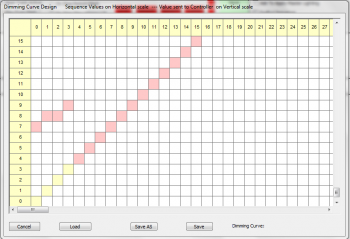
- To begin creating a Dimming Curve, click Library -> Dimming Curves.
- Figure 12-2 will appear.
- You can adjust the curve by left-clicking on the salmon colored cell (you may have to scroll down to see them) and then clicking on the cell where you want it to be.
- Sequence Values are on the horizontal scale; Controller Values are on the vertical scale. What this means is that you adjust the horizontal value for a dmx value and set it to the vertical value you want to go to the controller.
- Example: You want a value of 50% in the sequence to be the 25% value on the controller. So, click the colored cell on the horizontal scale line of 128 and move it to the vertical scale value of 64.
Saving/Modifying Dimming Curves
- To save your custom dimming curve, click the Save As button.
- HLS will automatically open the file dialog box in the Dimming Curves folder.
- Type a name for your curve and click Save.
- To modify a dimming Curve, open the dimming curve window (Library -> Dimming Curves).
- Click the LOAD button to load a previously saved dimming curve.
- Make needed changes, then click the "save" button or "Save as" to save under a new name.
Applying a Dimming Curve to a Channel
You can apply a Dimming Curve to single channels, or you can select a dimming curve and assign it to a group of selected channels. First, open the Channel Manager (Manage Channels -> Manage Raw Channels).
To apply to single channels:
- Right-click in the Dimming Curve cell for the desired channel.
- Figure 12-3 will appear. Select the appropriate dimming curve and click OK.


To apply to a group of channels:
- In the channel manager window, click Get Dimming Curve File (see Figure 12-4).
- Select the dimming curve you wish to load.
- Select the channels you wish to apply the dimming curve to by clicking and dragging down to highlight.
- Click Add Dimming Curve to apply the curve to the selected channels.
- Dimming curves will be assigned as in Figure 12-5.
RGB Dimming Curves
RGB Dimming Curves are similar to regular dimming curves, except you can set specific curves for each color value.
- Click Library -> RGB Dimming Curves. Figure 12-6 will open.
- Select Load and select individual channel dimming curve files for each color.
- Click New and name your file.
- Click Save to save it. Assign it to channels the same as with regular Dimming Curves.
Sane Default Curve
To help people get started on creating curves for LED lighting, a fairly sane default curve has been created. This curve is based on a thread in the DIYC forums that discussed dimming curves and appropriate DMX values for LED lights that will come closer to reflecting the dimming of incandescent lighting.[9]
This curve is based on white light and would need to be further refined for specific RGB Curves. Download here. Other members are encouraged to share their dimming curves as well.
| HLS User Manual and Reference Guide | ||
|---|---|---|
| Previous Page | Current Chapter | Next Page |
| Restoring a Sequence from Backup | Chapter 12: Reference Guide | Crosshair Cursor |
</noinclude>
Crosshair Cursor (12Z)
The Crosshair Cursor is a useful tool for being able to sync up exact times for channels and with the visual audio representation. Or to sync channels with beat tracks. All with out having to scroll up or see it perfectly aligned.
To activate the Crosshair Cursor, you can click the Defaults menu and select Crosshairs ON/OFF. Or, a more simple method, is to Toggle the cursor by pressing T. This allows you to quickly turn it on and off as you need. Figure 11.2-1 shows what it looks like when activated.
The HLS Toolbar (12Z)==
- Change RGB Color Effects: Select RGB channel effects you wish to colorize. Click the large rectangle and select the desired color. Click the Change RGB Color Effects button and the selected effects will be changed to the desired color. Your effects and their values will remain the same.
- Chase RGB Vertical: Create a "color chase" on a vertical plane.
- Select multiple channels with pre-existing effects on a vertical plane.
- Click the first of the two color blocks in the row.
- Set beginning and ending colors for color wheel chase.
- Click Chase RGB Vertical button to chase through the colors on the wheel vertically through the selected channels.
- Chase RGB Horizontal: Create a "color chase" on a horizontal plane.
- Select multiple cells of a pre-existing effect on a horizontal plane.
- Click first of two color blocks in the row.
- Set beginning and ending colors for color wheel chase.
- Click Chase RGB Horizontal button to chase through the colors on the wheel horizontally through the selected grid cells.
Master Lighting Channel (In Process)
Introduction
- A Master Lighting Channel is an overall light control.
- It controls the total light intensity on the "stage".
- A Master Lighting Channel could be used for a slow fade at the beginning or end of a song, or for a total control of bringing the intensity down for the whole sequence, etc.
- There will always be a Master Lighting Channel visible in the Channel Manager in HLS. You don't have to use it if you don't want to, but you cannot delete it.
- If you apply no effects to the channel, then that means lights will run at whatever intensity they are set at in the sequence.
Using the Master Lighting Channel in HLS
- To use the Master Lighting Channel, it must first be added to a display group.
- Once the display group you have added it into is active, you will be able to add basic effects to that channel just like a regular HLS channel.
- For example, you can add a 10 second ramp down at the end of your sequence in the Master Lighting Channel. This will slowly fade all of your channels, no matter what effects they may be demonstrating during that period.
- Note: Any cells with NO effect in them on the master lighting channel means the channels will demonstrate the intensity set in the sequence.
Activating a Master Lighting Channel
- To activate a Master Lighting Channel, when you export illumination data, you will be asked if you want to make the Master Lighting Channel active.
- Check the box to make the channel active. Otherwise, your sequence will ignore any effects placed on that channel and will run lights with regular intensity.
