Ren-W Configuration Concepts
Ren-W Theory of Operation
- 1. A packet of RS-485 serial data arrives at the Ren-W’s J1 RJ45 jack. The source of the RS-485 serial data is unimportant; it may be directly from the computer or from another Renard SS controller. The J1 jack conforms to the Renard SS’ J1 where -485 data is pin 4 and pins 1and 2 are ground (Ren-W does not use pin 5 of J1).
- 2. J1’s pin 4 connects to the XBee’s DIN (pin3) via a simple zener diode circuit to further protect the XBee’s maximum input voltage of 3.3vdc.
- 3. The XBee module transmits the data stream wirelessly to one or more designated receivers.
- 4. The receiving XBee processes its received data and ports the stream to its DOUT (pin 2), which in turn is connected to the MAX232’s T1IN (pin 11).
- 5. The MAX232 translates the XBee’s stream into an RS-232 serial signal and ports it to its T1OUT (pin 14) which is connected to pin 4 of the Ren-W’s J2 jack (pins 1-2 are ground).
- 6. The Ren-W’s J2 conforms to the Renard SS’ J2 input which receives RS-232 serial data on pin 4.
- 7. The Renard controller processes the command as it normally would, but if the command is for a channel that it does not have, it passes the unused control command on to the next Renard controller via RS-485 pin 5 of its J1 (data out) jack.
- 8. The Renard controllers’ J1 jack is connected to the Ren-W J1 jack via standard cat5 cable in the same fashion as one Renard controller daisy chaining to another.
- 9. The unused serial data received on pin 4 of this Ren-W’s J1 on this Renard controller restarts the sequence on this Ren-W at step #1, which XBee module is configured to transmit to the next Ren-W in the chain and the process repeats itself until there are no more Ren-Ws to receive data.
- Note: Throughout this document you may notice the similarity of part naming conventions of the Ren-W to the Renard SS controller. This is by design. It’s easier to remember that J1 plugs into J1, J2 into J2, and as you’ll later discover in the section titled “Powering the Ren-W board”, power connector JP3 plugs into JP3. (If using a Ren-C/595 or Ren-C/Grinch system, JP3 connects to one of the Ren-C’s vcc pins.)
PAN ID concepts
- Basic Concept: XBee radios have a configuration option called the "PanID." On an XBee network, this works similarly to the SSID of a wi-fi network. Only units that have the same PanID can communicate with one another. However, each radio has its own address ID as well. By changing either a radio's individual address or the PanID, you control which units receive what signal. By creative use of radio addressing, you can create a one-to-many or one-to-one communication scheme. Note however, that instead of using individual addressing of each radio, a far better and more convenient method is to simply use one transmitting XBee to globally send the data out to all receivers simultaneously and then use start address firmware in the respective controllers to capture the channels the controller is supposed to use.
Global broadcast

- Configure all XBee modules with the same PAN ID (or just keep the default 3332). When the first one (e.g. the "master") transmits the Vixen control signals, all the other XBee modules will receive them simultaneously, and all the Renard SS controllers will respond identically. Example: for a 24-channel system, if SS8 controllers are mixed with SS16s and SS24s, the SS8s will respond to Vixen channels 1-8, the SS16s will respond to Vixen channels 1-16 and the SS24s will respond to Vixen channels 1-24.
- In a global broadcast mode, only one Ren-W board is used as the master transmitter and all the other Ren-W boards are receivers only, so each Ren-W board would require only one XBee module. The design of a global broadcast network looks like the example above.
- A special version of Renard firmware is available that allows using the global broadcast mode while still retaining individual channel selectability with each controller. The feature is called the Renard Start Address and the configuration guide can be found here: Renard Start Address Configuration Guide.
Point-to-point (PTP) broadcast
Note: Because Start_Address firmware can be used in a Renard Controller, Global Broadcast mode is vastly preferred to PTP mode, and PTP is generally not used. It is explained here, but doing so makes wireless connections quite a bit more complicated, not to mention more expensive since nearly twice as many Xbee radios are required to make it work.
- PTP mode enables the "daisy-chain" function that allows multiple Renard SS controllers to have their own ranges of channels which is more in keeping with the way most people use Renard controllers. Two PTP options are available: the standard and alternate methods. To accomplish this, think of the wireless system as a replacement for the cat5 wires: the RJ45 plugs are the individual XBee modules and the cat5 wire is replaced by the wireless radio signal. The first SS controller gets the first group of Vixen channels, the next controller in the chain gets the next group, etc. just as if the controllers had been daisy chained using cat5 cables. To configure the Ren-W network to simulate the cat5 wiring scheme, the first Ren-W board needs to be a transmitter only. It's PAN ID must be set to the same number as the next Ren-W's receiver module. (The second Ren-W would have two XBee modules -- one to receive and the other to retransmit the Vixen commands to the next Ren-W board) The second Ren-W board's XBee transmitter would have a different PAN ID than its receiver, and the third Ren-W board's receiver would have the same PAN ID as the second Ren-W's transmitter. This scheme continues until the last Ren-W which would be only a receiver and have only one XBee module.

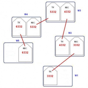
- In the above standard PTP example, imagine that Ren-W1 is the main transmitter connected to the computer and all the other units are 24-channel Renard SS24, for a total of 96 channels.
- Ren-W1 (main transmitter) has PAN ID (3332), which matches the W2’s receiver so the two can communicate with one another. Therefore, W2 takes Vixen channels 1-24 and passes 25-96 on to the next Ren-W in the chain.
- The W2’s transmitter (PAN ID 4332) communicates with the W3’s receiver. Being the second controller in the chain, the W3 takes Vixen channels 25-48 and passes 49-96 on to the next Ren-W in the chain.
- The W3’s transmitter (PAN ID 5332) communicates with the W4’s receiver. Being the third controller in the chain, the W4 takes Vixen channels 49-72 and passes 73-96 on to the next Ren-W in the chain.
- The W4’s transmitter (PAN ID 6332) communicates with the W5’s receiver. Being the fourth controller in the chain, the W5 takes Vixen channels 73-96.
- Summary: the standard PTP method uses matching pairs of PAN IDs to determine which modules connect to one another. Repeater Ren-Ws must each have two XBee modules using the PANID example above.
Alternate PTP Configuration
- While the other three XBee configuration changes remain the same, instead of changing the PAN ID, this configuration option uses the XBee’s internal serial numbers to configure the point-to-point routing. The manufacturer assigns each XBee module a unique serial number which is expressed as two values: serial number high and serial number low. The alternate PTP configuration assigns the transmitting module’s “Destination Address High” and “Destination Address Low” to the serial number high and serial number low of the intended receiving module. The PAN IDs of all modules on the network must remain identical. In actual practice one can simply set the receiving radio's "My Address" setting and then set the "destination low" address to the "My Address" setting of the radio it's supposed to transmit to.
- This method is a bit more cumbersome than the normal PTP method but it results in a more private, secure network design. In a way, the alternate PTP method is similar to a dedicated TCP/IP addressing scheme for a computer network.
- Summary: the alternate PTP method uses XBee serial numbers or "My Address and destination low" to determine which pairs of modules connect to one another while keeping the PAN ID identical across all XBee modules. In addition, only one XBee module is needed per Ren-W board if the board is set as an E-mode repeater.
E-mode repeater:
- To use the Ren-W as an E-mode repeater, connect a jumper shunt across JP5 and use only one XBee module in the TX (left) position. You must also also use the alternate PTP configuration method throughout your Ren-W network.
Additional Ren-W Links