Ren-W Troubleshooting
The Ren-W circuit board is a very simple design but good soldering technique is still extremely important.
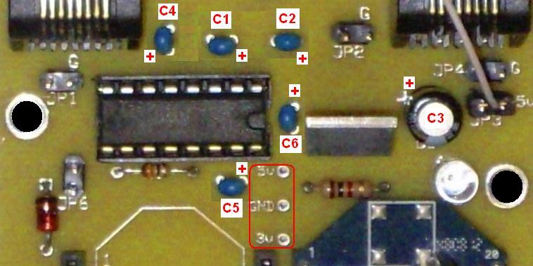
Voltage Measurements: three test points are just below pin 16 of the MAX232 chip/socket:
- Be certain that the following components are mounted on the board properly:
- The notch on the MAX232 chip faces to the right, toward the U1 voltage regulator.
- The zener diode (D1) has the black stripe on the TOP, next to the JP6 header pins.
- The 3.3 voltage regulator (U1) has the metal tab facing up, toward the JP2 header pins.
- The electrolytic capacitor (C3) has the - stripe facing DOWN toward the LED, which means the + side is up toward the J2 jack.
- The LED (D2) while not shown in this photo, has the cathode (flat side) facing the mounting hole to its right.
- Resistor R1 (33 ohms) is immediately below the MAX232 chip. The resistor has no polarity concerns.
- Resistor R2 (1k ohms) is immediately below the U1 voltage regulator. The resistor has no polarity concerns.
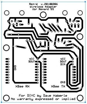
- When you study the underside (copper) side of the circuit board, a few things become readily apparent:
- Very few pins of the XBee radio modules are actually used; most are unused and serve only to hold the header pins securely.
- The solder pads for the XBee headers are very small; accurate and careful soldering is a must to prevent solder bridges. A solder bridge could easily prevent the XBee radio from functioning properly and could damage it.
- Easy Mistakes to Make
- Plugging the XBee module into the wrong side of the board. Remember:
- A receive-ONLY Ren-W has the XBee mounted in the RX (right) side and no jumper is on JP5. The cat5 cable is plugged into J2 and into the J2 socket of the Renard SS controller (the controller's RS-232 IN port)
- A transmit-ONLY Ren-W has the XBee mounted in the TX (left) side and no jumper is on JP5. The cat5 cable is plugged into J1 and into the J1 socket of the Renard SS controller (the controller's RS-485 OUT port).
- An E-Mode Repeater has is exactly the same as a transmit-only board but JP5 is jumpered instead. Cat5 cables connect both jacks J1 and J2 to the Renard controller's RS-485 OUT and RS-232 IN ports respectively.
- Connecting J1 to the Renard controller for a receive-only Ren-W won't work because a receive-only Ren-W uses J2 for the cat5.
- Connecting J2 to the Renard controller for a transmit-only Ren-W won't work because a transmit-only Ren-W uses J1 for the cat5.
- Misconfiguring the 16-bit address of an XBee module.
- Setting the destination address of an XBee module to the wrong address.
- Changing the PANID to the wrong value; remember, only radios with the same PANID can communcate with one another.
- Resetting the XBee radio back to the default settings and forgetting to change the baud rate back to the 57,600 that Renard uses.
- Mounting the Ren-W so the antenna is too close to a transformer or even a triac on the Renard controller can cause erratic transmission and/or reception behavior.
Additional Ren-W Links

