Ren-W XBee Radio Configuration
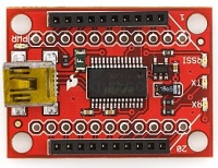
XBee Explorer Programmer
- You will need the free XCTU software from Digi International (www.digi.com) Software download: XCTU SOFTWARE. You also will need an XBee programming board. An inexpensive programming board is available from SparkFun Electronics (www.sparkfun.com - XBee USB Explorer, SparkFun part # WRL-08687, about $25. The same board is available from the Robot Shop for $20 www.robotshop.com) Other programming boards are available and prices vary widely.
- Alternately, you can also configure the XBee manually using a Ren-W board; information about manual configuration appears later in this document.
- 1. Verify that the programmer board is unplugged from the USB port, and plug the XBee module into the board.
- 2. Connect the programming board into the computer's USB port. Wait a few moments for the computer to recognize it.
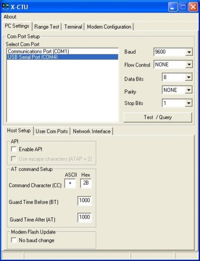
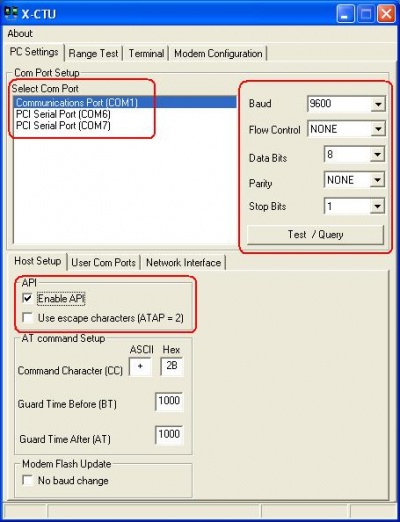
- 3. Start the XCTU software. Choose the proper communication port into which the programmer board is plugged.
- 4. Use the default communication parameters to begin (9600 baud, no flow control, 8 data bits, no parity, 1 stop bit). These are the default parameters for all XBee modules right out-of-the-box.
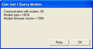
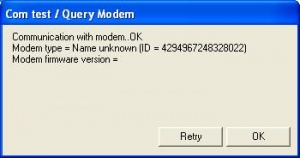
- 5. Connect to the XBee module by clicking the Test/Query button. After a few seconds, a confirmation box will appear that communication was successful. The box will also display the type and firmware version the XBee module is using. Close the test/query box to continue. Note: if a connection is not made, verify that the correct com port and baud rate was selected and try again. If still unsuccessful, retry using a different baud rate.
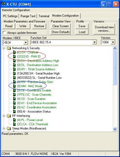
- 6. Select the Modem Configuration tab.
- 7. Click the Read button. In a few moments, the screen will display multiple configuration items.
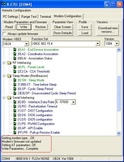
- 8. Only five items need changing: PAN ID, MAC Mode, Interface Data Rate, Parity and Packetization Timeout (scroll down the XCTU screen to view more settings).
- PAN ID: this is akin to a "domain" for a computer network, but for XBee, the ID is numerical instead of text. The default is 3332 for all XBee modules, but you can change it to a different number if you wish or if another XBee network is in use nearby. Note that only modules with the same PAN ID can communicate with one another and that the easiest way to separate one XBee network from another is by changing the PAN ID. (Example: the Helix controller also uses the XBee radio modules; if you were using both Helix and a Ren-W, you should use a different PAN ID for the Ren-W than the Helix system.) See PAN ID concept notes on the previous page.
- MAC Mode: choose option 1 – 802.15.4 No ACKS. While all the modes function, this setting is the fastest for streaming data.
- Interface Data Rate: this is the speed at which the XBee will communicate with the Renard SS controllers. Set this to 57600 for best performance. While the maximum setting for both a Renard and an XBee is 115,200, XBee radios are designed to provide up to 80kbps streaming throughput; setting to 115,200 may cause erratic behavior.
- Parity: this setting may or may not be visible on your screen. If it is not available, you should upgrade your XBee firmware to version 10E6 to solve the problem. Once the Parity setting is available, set it to MARK PARITY.
- Packetization Timeout: set to zero (the default is 3). A zero setting makes the XBee perform faster.
- 9. When changes are complete, click the Write button near the top of the XCTU screen to save the changes to the XBee’s internal memory. A progress bar will appear and in a few moments, the completion message will appear such as the one in the lower left corner of this screen:
- 10. Because the XBee's communication parameters have changed, you can return to the first screen (steps #3-4 above), change the communication parameters to 57,600 baud, Mark parity and 2 Stop bits, requery the modem and reconnect to it to check your settings.
Setting an XBee Module's Address
- Connecting to all XBee modules simultaneously is easy: just set the PANIDs on each module to the same number. However, if you want to create a daisy chain network architecture where one module transmits to a specific next module, and so forth, you need to go a little further.
- If you have two modules on each Ren-W board (a real luxury because of the added expense!), you can simply set the PANIDs of the two modules that will communicate with one another to the same PANID. See the "Point to Point" broadcasting example on the Ren-W Configuration Concepts page.
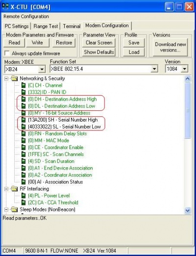
- However, in Alternate PTP mode with only ONE XBee module installed on a Ren-W board as an E-Mode Repeater (XBee module in the TX position and jumper on JP5) XBee addressing is used instead. With addressing, you have multiple options:
- Notice the 16-bit source address option in the above window. You can insert a numerical address of your choosing here, such as 1001, 1002, 1003, etc. and leave the PANID the same for all modules. To create a daisy chain network, you would assign the "destination address low" of the first module to be the 16-bit address of the next module. You would continue this logic throughout your XBee network by assiging a specific 16-bit address to each module and then assigning the desired destination addresses.
- Instead of assigning a 16-bit source address of your own, you may choose to use the predefined serial numbers instead. If you do, be sure to use both the serial number high and serial number low of the receiving module as the transmitting module's destination address high and destination address low. Using the serial numbers makes the network the most secure it can possibly be because no two XBee modules are manufactured with the same serial number high and low.
- TIP #1: Be sure to write each radio's 16-bit address and it's assigned destination address on a piece of tape and either tape it to the XBee itself or to your enclosure so you know which radio transmits to which.
- TIP #2: By defining two or more XBee modules with the same 16-bit address, you can control them simultaneously from only one radio. However, don't assign multiple XBees to the same destination address or the receiving XBee may receive different commands from two different sources; the result will likely be confusion.
Manually Configuring an XBee Module with the Ren-W
- An XBee can be programmed manually directly from your computer's serial port (using an RS-485 converter) and a Ren-W board if you do not have an XBee programming board. However, this practice is somewhat difficult as there is no facility in the Ren-W for duplex communication with the XBee module, and you will be unable to "read" the XBee's settings to discover what they are. However, out of the box, an XBee module is factory pre-set at 9600 baud, 8 data bits, 1 stop bit and no parity.
- You will need a terminal program. The free XCTU software from www.digi.com includes a terminal program or you can use Windows Hyperterminal. XCTU is easier to use and is highly recommended as you have fewer configuration settings to contend with than with Hyperterminal.
- You may also want the XBee documentation that explains the AT command set the radio uses. This is also available from www.digi.com.
- The example below displays the method for setting the XBee module to the proper communication settings.
- 1. Plug the XBee module into the XBee TX (left) side of the Ren-W board.
- 2. Plug the cat5 cable from your RS-485 connection into the J1 jack of the Ren-W board. This is on the XBee TX (left) side of the board as well.
- 3. Make sure the Ren-W is powered up.
- 4. Start the XCTU software.
- 5. At the PC Settings screen, choose the correct com port for your computer and set the baud and other communication parameters to those of the XBee on the Ren-W board (see picture above).
- 6. Check the API box to "Enable API." This checkbox is on the far left side of the PC Settings tab about half-way down the screen. Leave the Use escape characters box unchecked (see picture above).
- 7. Click the Test/Query button. If the communication parameters match the module, you should receive a connection message that displays the serial number of the XBee radio but not much else (see picture above).
- 8. Select the Terminal tab.
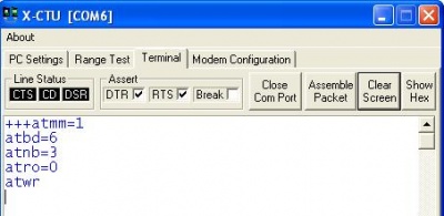
- 9. Type +++ by itself but DO NOT PRESS THE ENTER KEY. Wait about 2 or 3 seconds.
- 10. Type ATMM=1 and press ENTER, then wait about 2 seconds. This command sets the MAC mode to the No Acks setting.
- 11. Type ATBD=6 and press ENTER, then wait about 2 seconds. This command sets the BAUD rate to 57,600.
- 12. Type ATNB=3 and press ENTER, then wait about 2 seconds. This command sets the PARITY to MARK.
- 12. Type ATRO=0 and press ENTER, then wait about 2 seconds. This sets the packetization timeout to zero.
- 13. Type ATWR and press ENTER, then wait about 5-10 seconds. This writes the changes to the XBee's internal memory.
- 14. Remove power to the Ren-W board so when you restart it, it has a cold boot.
How to change the XBee's PAN ID:
- Access the XBee as described in steps 1-8 above. Remember to change the baud rate to 57600 or the software will not connect to it.
- Type +++ by itself but DO NOT PRESS THE ENTER KEY. Wait about 4 or 5 seconds.
- Type ATID=2255 and press ENTER on your keyboard. Wait about 4 seconds. This sets the radio's PAN ID to 2255 (in this example). You may substitute 2255 with any 4-digit number of your choice.
- Type ATWR and press ENTER on your keyboard. Wait about 10 seconds. This command "writes" the setting into the XBee's internal memory.
- The XBee's PAN ID has now been changed to the number you selected. Remember that only XBees having the same PAN ID can communicate with one another. Power the Ren-W off so the XBee gets a cold restart.
How to change the XBee's OWN address:
- Access the XBee as described in steps 1-8 above. Remember to change the baud rate to 57600 or the software will not connect to it.
- Type +++ by itself but DO NOT PRESS THE ENTER KEY. Wait about 4 or 5 seconds.
- Type ATMY=1234 and press ENTER on your keyboard. Wait about 4 seconds. This sets the radio's address to 1234. You may substitute 1234 with any 4-digit number of your choice.
- Type ATWR and press ENTER on your keyboard. Wait about 10 seconds. This command "writes" the setting into the XBee's internal memory.
- The XBee's own address has now been changed to the number you selected. Power the Ren-W off so the XBee gets a cold restart.
How to change the XBee's DESTINATION address:
- Access the XBee as described in steps 1-8 above. Remember to change the baud rate to 57600 or the software will not connect to it.
- Type +++ by itself but DO NOT PRESS THE ENTER KEY. Wait about 4 or 5 seconds.
- Type ATDL=3456 and press ENTER on your keyboard. Wait about 4 seconds. This sets the radio's destination LOW address to 3456. You may substitute 3456 with the 4-digit address of the module this XBee should transmit to. Setting the destination address makes the XBee transmit ONLY to that address and only XBees with that address (3456 in this example) will receive the signal.
- Type ATWR and press ENTER on your keyboard. Wait about 10 seconds. This command "writes" the setting into the XBee's internal memory.
- The XBee's destination address has now been changed to the number you selected. Power the Ren-W off so the XBee gets a cold restart.
Making your own Ren-W Explorer Board/Cable
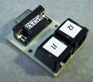
- The connections are as follows:
- 1. You must make the RS485 patch to the board for this to work (see troubleshooting page for info)
- 2. RS232 pin 5 (gnd) connects to Ren-W J1 pin 1.
- 3. RS232 pin 3 (TX) connects to Ren-W J1 pin 4.
- 4. RS232 pin 2 (RX) connects to Ren-W J2 pin 4.
- 5. The XBee radio must be in the TX (left) side of the Ren-W and of course, the board must be powered-up.
- 6. Ren-W's JP5 must be jumpered.
- 7. Use the XCTU software as normal; be patient as the software is looking for handshaking signals and you'll probably encounter a delay. Alternately, you can use Windows HyperTerminal to make your connection and program it that way.
How To Update XBee Firmware
- At the time of this writing, version 10E6 was the most current version of the XBee firmware. It is highly suggested that users update all their XBee modules with this version.
- 1. Using the USB XBee Explorer board will be faster and more secure than any other board as it is designed for this.
- 2. Open the XBee with the XCTU software and view the XBee's settings screen.
- 3. Click the RESTORE button, then click WRITE. This will restore the radio to factory defaults, a requirement for changing the firmware.
- 4. Change the XCTU software setting to reconnect to the radio, then redisplay the XBee's settings screen.
- 5. Click the ALWAYS UPDATE FIRMWARE box.
- 6. In the Version box (right side of the screen), choose version 10E6
- 7. Here's were it can get a little strange... Click the WRITE button.
- a) If the radio gives a "disconnect" kind of message on the bottom of the screen, do steps b-g below. If it does not, it will update the firmware directly, then go to step #8.
- b) Leave the Explorer board plugged in but unplug the XBee from the Explorer board.
- c) Click the WRITE button again, even though the radio is not plugged in. Wait a few moments, and a screen should appear that has a lot of words and options. Just do the next step quickly.
- d) Plug the XBee radio back into the board. The screen should disappear, and you should get a note on the screen that the XBee is "initializing." After that, it will go to programming.
- e) Another screen with text and options may appear. Unplug the radio again from the Explorer board, count to 1 and plug it back in.
- f) It should then read the AT commands to display the XBee's settings page again.
- g) Continue with the next step.
- 8. Uncheck the ALWAYS UPDATE FIRMWARE box.
- 9. Make appropriate changes to the XBee's settings to match your display. Version 10E6 of the firmware will display a new setting in the serial portion of the setting screen: a PARITY setting. If you use a wireless Ren64 in your display, you should read the troubleshooting page about the special settings necessary for the Ren64.
- 10. Click WRITE to write the settings to the radio. You will get an error message as it tries to reread them because the XCTU software still has the old settings and can't connect to it.
- 11. Change the XCTU settings to match the baud and/or parity settings, reconnect to the radio again and redisplay the settings you changed to verify they were successful.
- 12. Now the XBee is ready.
What Usually Goes Wrong When Two Radios Don't Communicate
- The world of XBee radio addressing can become extremely complicated, and troubleshooting it can be a doggedly frustrating experience. START SLOW AND SIMPLE. Get TWO radios talking together -- change only the basic three settings and do nothing with individual radio addressing until you are comfortable understanding how to configure them. In almost every case, you will discover that a non-communication situation is caused by an addressing or baud rate problem. Secondarily, once the radios are in the Ren-W boards and connected to controllers, you may forget which is a transmitter, which is a receiver, which is a repeater, or you'll find you have a board set up to be a receiver but the XBee is in the TX side. Or you may have a radio set up to be a transmitter but it's plugged into the controller's RS-IN jack, which is for a receiver. GO SLOWLY, TAKE YOUR TIME.
Additional Ren-W Links
